ITA-2000 User Manual
/ 用户手册
56
A.1
Programming the Watchdog Timer
/看门狗定时器
编程
The ITA-2000's watchdog timer can be used to monitor system software operation
and take corrective action if the software fails to function within the programmed
period. This section describes the operation of the watchdog timer and how to pro-
gram it.
ITA-2000 看门狗定时器可用于监控系统软件操作,并在编程过程中出现软件故障时采
取适当措施。本章节介绍了看门狗定时器操作以及如何编程。
A.1.1
Watchdog Timer Overview
/ 看门狗定时器概述
The watchdog timer is built into the super I/O controller W83627DHG. It provides the
following user-programmable functions:
Can be enabled or disabled via user program
Timer can be set from 1 to 255 seconds or 1 to 255 minutes
Generates an interrupt or resets signal if the software fails to reset the timer
before time-out
看门狗定时器内置于高级 I/O 控制器 W83627DHG,提供了以下用户可编程功能:
可通过用户编程启用或禁用
定时器可设置为 1
~
255 秒或 1
~
255 分钟。
在软件复位定时器超时时产生中断或复位信号
A.1.2
Programming the Watchdog Timer
/ 编程看门狗定时器
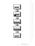
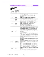
The I/O port address of the watchdog timer is 2E (hex) and 2F (hex). 2E (hex) is the
address port. 2F (hex) is the data port. You must first assign the address of register
by writing an address value into address port 2E (hex), then write/read data to/from
the assigned register through data port 2F (hex).
看门狗定时器的 I/O 端口地址为 2E (hex)和 2F (hex)。2E (hex)为地址端口。2F
(hex)为数据端口。用户必须首先通过向地址端口 2E (hex)写入一个地址值分配一
个寄存器地址,然后通过数据端口 2F (hex)向 / 从分配的寄存器写入 / 读取数据。
Summary of Contents for ITA-2000
Page 8: ...ITA 2000 User Manual viii...
Page 12: ...ITA 2000 User Manual xii...
Page 16: ...ITA 2000 User Manual 4 1 5 Dimension Diagram Figure 1 1 Dimension diagram...
Page 28: ...ITA 2000 User Manual 16...
Page 29: ...Chapter 3 3 BIOS Operation BIOS This chapter describes how to set BIOS configuration data BIOS...
Page 60: ...ITA 2000 User Manual 48...
Page 61: ...Chapter 5 5 System Setup This chapter introduces the instal lation process...
Page 67: ...Appendix A A Programming the Watchdog Timer...
Page 79: ...Appendix B B Examples of the CAN Transfer tool CAN...

