background image

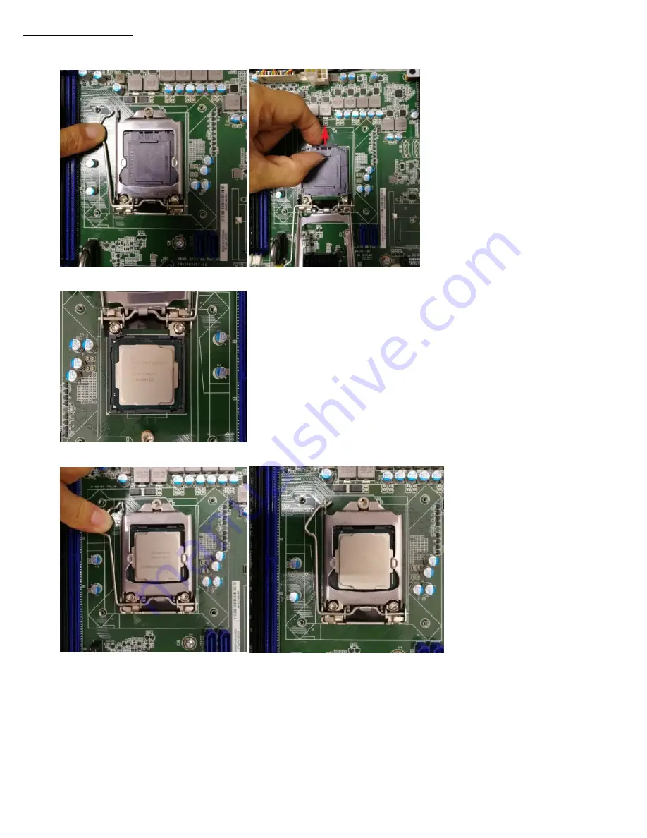
Installing the CPUs 

1.  Taking one CPU at a time, remove the protective shield, if present, and press the load lever and move it out till it is clear of the 

retention tab, and raise it. 


2.  Make sure that alignment triangle on the CPU lines up with the correct corner on the socket, and ease the CPU into place. 


3.  Close the load plate and push the load lever back down until it engages the retention tab. 


Summary of Contents for FWA-3033-00A1R

Page 1: ...y capacity PCI Express 2 PCIe x8 Size slots for HL FL PCIE card one slot bandwidth is PCIEx4 Gen3 another is PCIEx2 Gen3 1 Mini PCIE reserved on Riser Network Connectivity NMC Modules 2 NMC slots with PCIe Gen3 x8 Connectivity Management 6 8 LAN ports onboard by 10 100 1000 Base T Ethernet 4 SFP ports onboard SKU option Mass Storage 2 x 3 5 internal SATA HDD SSD 1 x M 2 2260 2280 Slot M Key Periph...

Page 2: ... Platform FWA 3033 00A1R Front view FWA 3033 00A1R Back view FWA 3033L 00A1S Front view FWA 3033L 00A1S Back view Set up 1 To unpack first remove 9 screws on the side of the machine by referring to the arrows below Installation ...

Page 3: ...s the load lever and move it out till it is clear of the retention tab and raise it 2 Make sure that alignment triangle on the CPU lines up with the correct corner on the socket and ease the CPU into place 3 Close the load plate and push the load lever back down until it engages the retention tab ...

Page 4: ... the arrow in the figure below 2 Refer to the figure below to attach the four screws diagonally on the Heatsink to the CPU bracket and then take out three screws from the accessory box to attach the Fan cover to the chassis 2 silver locks on both sides 1 black lock in the middle Installing the RAM 1 Insert the prepared memory into the DIMM slot and make sure that the card hook is in place ...

Page 5: ...then remove the HDD bracket 2 Take out the 4 teeth screws in the accessory box and refer to the figure below to attach the 3 5 HDD to the bracket 3 After installing the HDD bracket on the base confirm that the cables at the arrows in the figure below can be pulled 4 Use the removed 4 screws to lock the HDD bracket and plug the SATA cable and the Power cable from the power supply to the HDD ...

Page 6: ...rews from the accessory box and attach the HDD to the bracket with reference to the figure below 3 Confirm that the wire at the yellow circle in the figure below can be pulled and then fix the bracket with 4 screws removed 4 Plug the SATA cable and the power cable from the power supply into the HDD Two layers of the 2 5 HDD installation 1 Take out and install the HDD bracket and shockproof rubber ...

Page 7: ...cable to the edge of the chassis the yellow box in the figure below and then attach the bracket to the base 4 Connect the SATA cable and the Power cable from the power supply to the HDD Install M 2 1 Take out one screw from the accessory box and fix the installed M 2 lock on the silver pillar of the motherboard The expansion of the riser card 1 This card has a Mini PCIE and PCIE slots can be used ...

Page 8: ...st and the long card doesn t need 3 Use 1 screw taken from the accessory box to attach the half size mini PCIE lock to the riser card 4 Then use three removed screws to attach the riser lock back to its original position PCIE extension 1 Remove 4 screws at the arrow below and remove the blanking module 2 Remove one of the screws on the blanking module shown by the arrow in the figure below and rem...

Page 9: ... to confirm whether the pins of the lower expansion card touch the base If so you need to do insulation treatment before installing Installing HDD If the riser card position need to install the HDD you need to remove the riser card first 1 Refer to the figure below to remove three screws at the arrow and pull out the card 2 Remove the copper post from the accessory box and lock it on the base chas...

Page 10: ...e accessory box Refer to the figure below connect the SATA power cable to the power 4pin connector pointed by the arrow and connect the cable along the dotted line to the HDD One end of the SATA data cable is connected to the motherboard and another end connect to the HDD 7 Attach the Fan cover to the base and arrange the extra SATA Power cable Installing the NMC 1 Remove the NMC blank by turning ...

Page 11: ... a way that people cannot step on it Do not place anything over the power cord The voltage and current rating of the cord should be greater than the voltage and current rating marked on the product 11 All cautions and warnings on the equipment should be noted 12 If the equipment is not used for long time disconnect it from the power source to avoid being damaged by transient overvoltage 13 Never p...

Page 12: ...ack mount instructions are included with the installation instructions a Elevated Operating Ambient If installed in a closed or multi unit rack assembly the operating ambient temperature of the rack environment may be greater than room ambient Therefore consideration should be given to installing the equipment in an environment compatible with the maximum ambient temperature Tma specified by the m...

Reviews: