


ARMA-C125-CRM
15
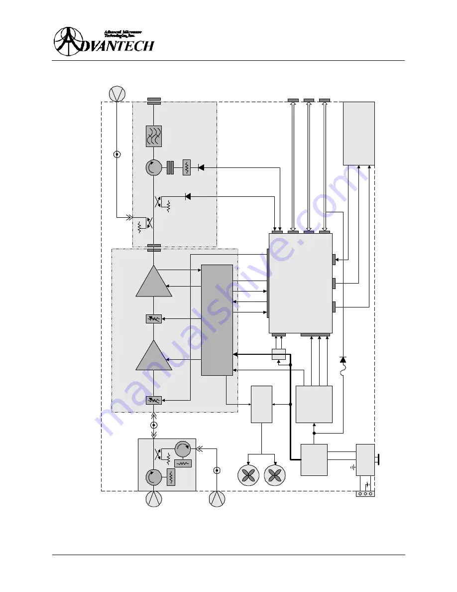
Figure 2
: Block Diagram
J1
RF
INPUT
J4
OUTPUT
MONITOR
J7
W/G OUTPUT
TEMP
SENSOR
GAIN
CONTROL
COOLING
FANS
+12V,
-9V
+12V,
-9V
HPA ASSEMBLY
OUTPUT WAVEGUIDE
ARM ASSEMBLY
POWER CONDITIONER
BOARD ASSEMBLY
J5
AC
LINE
+ 12V
- 9V
- 15V
+ 15V
+ 5V
J2
SERIAL
I/F
J3
DISCRETE
I/F
J6
REDUNDANT
I/F
CURRENT
SENSOR
GND
TEMP
SUMALARM
MUTE
40 dB
30 dB
20 dB
+ 12V
MAIN
POWER
SUPPLY
SECONDARY
POWER
SUPPLY
FRONT PANEL
KEY PAD
LEDs
DISPLAY
SPEED
CONTROLLER
CIRCUIT
BREAKER
11.5 - 60 V
- 9V
LNA
HPA
TEMP.
COMPENS.
ISOLATOR
FILTER
MONITOR
AND
CONTROL
REFLECTED
POWER
DETECTOR
OUTPUT
POWER
DETECTOR
THERM
12 V
J8
INPUT
MONITOR
A
B
C
GAIN
CONTROL


