background image

10 

STEP 3: Securing the power supply cable to the strain relief rail 


  Attach the matching 

cable grommet

 to the power supply 

cable.  

NOTICE

: The cable grommet must completely surround the 

cable. The opening of the cable grommet must be slightly 
smaller than the cable diameter. If the opening is too large or 
too small, the sealing of the device will not be ensured. 


As a delivery standard, screws and cable clips are fixed on the DLT-V6210 

strain relief rail. 

  Unscrew and remove the screws and the cable clip fixed on the cable 

passage you want to use for the power supply cable.  

  Insert the power supply cable and the cable grommet in the cable passage of 

the strain relief rail. 

  Place the cable clip on the power supply cable. 

  Secure the cable clip to the strain relief rail using 2 pcs of Phillips screws 

(middle round screw head) M3x10L: 


  Tighten the mounting screws alternatingly. 


NOTICE

: Tighten the mounting screws sufficiently but on no account pinch or 

crush the cable. If you do, the cables may break or the cable insulation may 
get damaged. 


STEP 4: Connecting the USB, Ethernet, COM and antenna cables 

Proceed as described with the 

power supply cable

 above. 

  Attach the matching cable grommet to the cable. 

  Insert both components in the cable passage. 

  Secure it to the strain relief rail using cable clip and appropriate screws: 


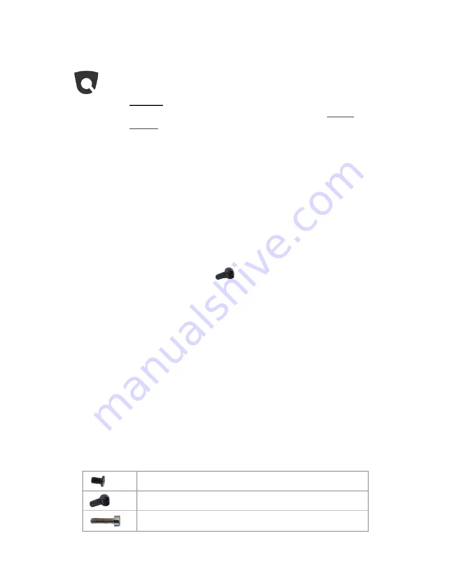
For thinner cables: Phillips screws M3x5L 


For regular cables: Phillips screws M3x10L 


For thicker cables: Hexagon screws M3x12L 

Summary of Contents for DLT-V6210

Page 1: ...d use Observe the intended use of the DLT V6210 e g No use in potentially explosive zones and on ships on railed vehicles no use in life supporting systems or security critical facilities Observe the required qualification This document is intended for qualified skilled personnel Only skilled personnel may put the DLT V6210 into operation Do not put the DLT V6210 into operation if it is damaged Do...

Page 2: ...vere injury CAUTION Danger that can lead to slight injuries 2 Technical data of DLT V6210 DLT V6210 Weight 3 2 kg Dimensions Width x height x depth in mm 285 x 256 x 70 height including antenna cap Operating temp 30 to 50 C Storage temp 30 to 60 C Relative humidity 10 95 non condensing Ambient temperature 25 C IP protection class IP65 Shock Vibration Class 5M3 according to EN 60721 3 5 US Highway ...

Page 3: ...ST A type 5 VDC 500 mA Fused at 0 5 A per channel Serial COM Max 115 200 Baud 16550A compatible 16 byte FIFO Supports EIA 232 E on external 9 pin D Sub connection 5V at Pin 9 CFast slot under the antenna cap Exercise special care when removing and re inserting the CFast card Only use CFast cards that have been approved by Advantech DLoG Opening the antenna cap Loosen the two screws of the antenna ...

Page 4: ...must be trained by skilled personnel and instructed about the operation of the device Operate the touchscreen with Clean dry fingers Clean dry thin gloves Suitable touch stylus Function of the front keys left side Power on off LCD Brightness up LCD Brightness down LED indication System Status LED Status System power on Static on System power off Off System over under temperature Blinking 0 2 sec o...

Page 5: ...anuals at www advantech dlog com WARNING Safety information about radiation emission This device emits high frequency energy abbreviation HF To protect people from HF radiation and to comply with country specific regulations Install the DLT V6210 so that persons maintain a minimum distance of 20 to 50 cm to the antenna Observe the applicable regulations for your deployment location country with re...

Page 6: ... to the DLT V6210 5 Install an easily accessible disconnecting device such as a switch close to the device 6 Connect all cables power supply etc 7 Seal cable passages with cable grommets and dummy grommets 8 Close the DLT V6210 with the cable cover 9 Install the DLT V6210 on the device mounting follow the mounting instructions In case of installing the DLT V6210 on vehicles Observe the vehicle man...

Page 7: ...er keyboard on the DLT V6210 Use suitable mounting material screws and washers Observe the maximum screw in depth of the holes of the DLT V6210 The recommended screw in depth of D x 1 always applies screw diameter x 1 ATTENTION Screws that are too long e g in the VESA mounting hole pattern can pierce the rear side of the DLT V6210 and cause irreparable damage to the device VESA mounting hole patte...

Page 8: ...ng regular cables to the terminal s strain relief rail Hexagon screw M3x12L H S D 5 5 H 3 SUS H Nylok For securing thicker cables to the terminal s strain relief rail Cable clip for securing the cables to the strain relief rail Cable grommets which openings have different sizes must be attached to all cables before the cables are inserted into the cable passages Dummy grommets for sealing up unuse...

Page 9: ...2 Secure the ring tongue of the power supply cable to the ground bolt important for correct grounding NOTICE To make sure the device is grounding correctly it is important to follow the correct order to put the components on the ground bolt as below from inside to outside 1 Place toothed washer first 2 Then put the ring tongue of the power supply cable flat side faces the DLT V6210 connector panel...

Page 10: ...mmet in the cable passage of the strain relief rail Place the cable clip on the power supply cable Secure the cable clip to the strain relief rail using 2 pcs of Phillips screws middle round screw head M3x10L Tighten the mounting screws alternatingly NOTICE Tighten the mounting screws sufficiently but on no account pinch or crush the cable If you do the cables may break or the cable insulation may...

Page 11: ...with dummy grommets so that they are sealed STEP 6 Attaching the cable cover Place the cable cover on the DLT V6210 housing slot Use 4 pcs of Phillips Screws M3x5L Lock the screws loosely into the holes of the cable cover Then fully tighten the screws alternatingly with 1 Nm torque Dummy grommets ...

Page 12: ...ity for defects limitation period for claims in relation to defects For more details please refer to www advantech dlog com by DLoG GmbH 2016 2018 All rights reserved We reserve the right to make changes to this document at any time and without prior notice DLoG GmbH is not liable for technical or printing errors or shortcomings in this document DLoG GmbH accepts no liability for damage caused dir...

Reviews: