NetVanta 1534/1544 Series
Physical Descriptions
61702590G1-34E
Copyright © 2013 ADTRAN, Inc.
21
Front Panel Features
Link/Activity LEDs
The link/activity LEDs labeled
1
through
24
are located above the 10/100/1000Base-T Ethernet
interfaces and indicates when there is activity on the interface. The link/activity LEDs labeled
25
through
28
indicate when there is activity on the SFP interfaces (located on the rear panel of the unit).
When the LED mode switch has been activated, these LEDs will display VCID status (future release).
Status LED
The
STAT
LED is located on the left side of the unit and indicates the unit’s status.
Redundant Power Supply LED
The
RPS
LED is located on the left side of the unit and indicates when the unit is receiving power
from the RPS.
VCID LED (Future Release)
The
VCID
LED is located on the left side of the unit and indicates that the port LEDs are displaying
VCID.
LED Mode Switch (Future Release)
The LED mode switch is located on the left side of the unit and is used to toggle Ports
1
through
28
between link/activity and VCID display modes.
10/100/1000Base-T Ethernet Interfaces
The front panel contains 24 10/100/1000Base-T Ethernet interfaces (RJ-45). These interfaces are
arranged in stacked pairs, with the numbers
1
through
24
screened from left to right directly above the
corresponding ports. Status LEDs for each stacked pair of interfaces are located directly over the
interfaces. Refer to
Table A-2 on page 47
for pinouts.
NetVanta 1544 Rear Panel Design
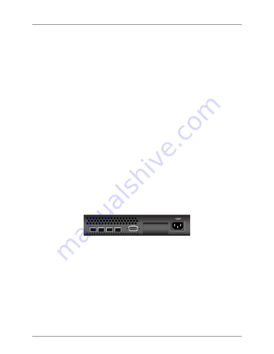
The NetVanta 1544 rear panel is shown below.
Figure 6. NetVanta 1544 Rear Panel Layout
Rear Panel Interfaces
SFP Slots
The rear panel contains four industry standard SFP slots for fiber or copper connectivity. These
interfaces are numbered
25
through
28
, support both 1000Base-X and 1000/2500Base-X SFP
modules, and their status LEDs are located on the front panel of the unit. Refer to
Table A-3 on page 48
for pinouts.
25
26
27
28
RPS - 12VDC


