Call StormTech at
860.529.8188
or
888.892.2694
or visit our website at
www.stormtech.com
for technical and product information.
22
6.0 Required Materials/Row Separation
6.1 CHAMBER ROW SEPARATION
StormTech SC-740, SC-310 and DC-780 chambers must
be specified with a minimum 6” (150 mm) space between
the feet of adjacent parallel chamber rows. No spacing is
required between the SC-160LP chambers. Increasing the
space between rows is acceptable. This will increase the
storage volume due to additional stone voids.
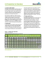
6.2 STONE SURROUNDING CHAMBERS
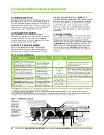
Refer to
Table 8
for acceptable stone materials.
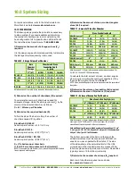
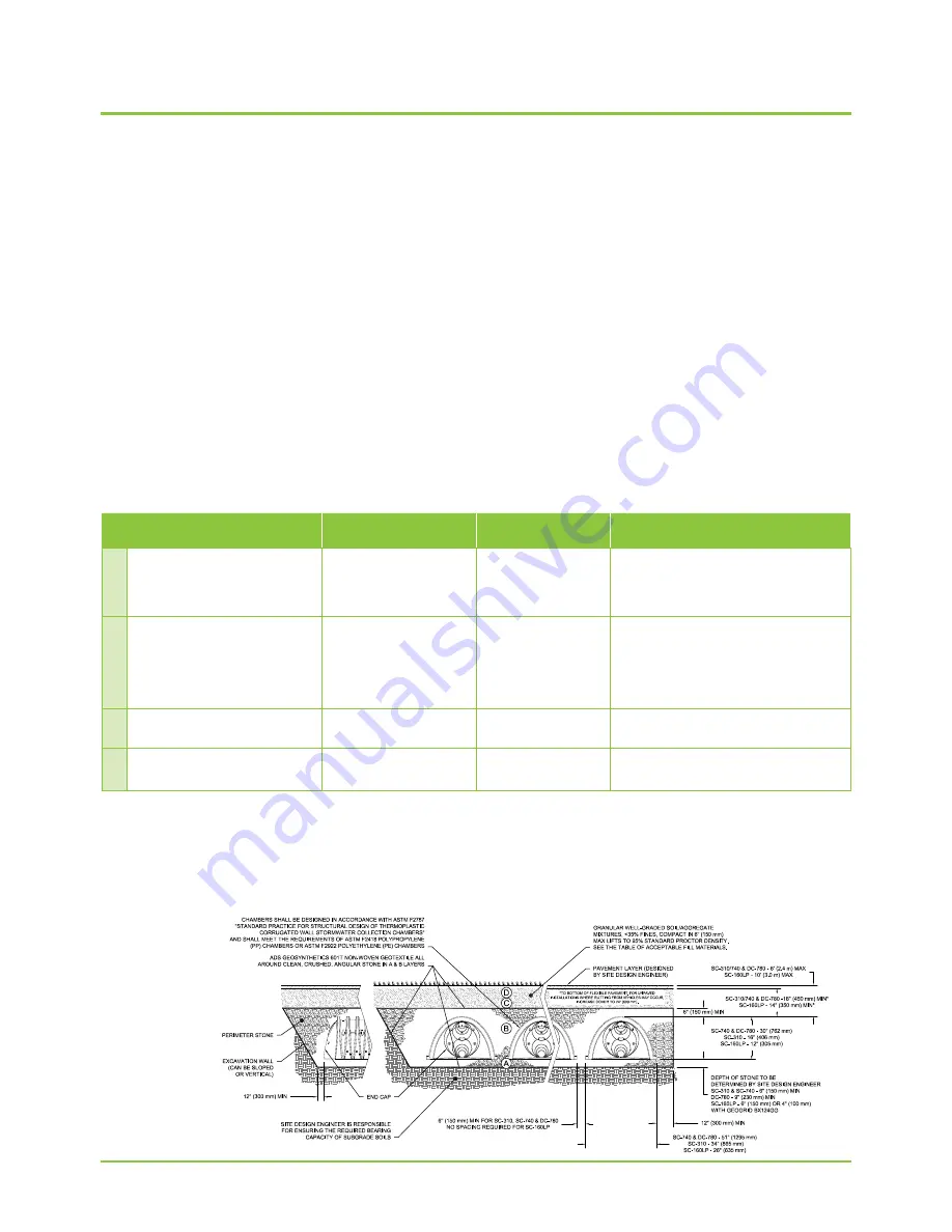
StormTech requires clean, crushed, angular stone below,
between and above chambers as shown in
Figure 6
.
Acceptable gradations are listed in
Table 8
. Subrounded
and rounded stone are not acceptable.
6.3 GEOTEXTILE SEPARATION REQUIREMENT
A non-woven geotextile that meets AASHTO M288
Class 2 Separation requirements must be applied as a
separation layer to prevent soil intrusion into the clean,
crushed, angular stone as shown in
Figure 6
. The
geotextile is required between the clean, crushed, angular
stone and the subgrade soils, the excavation’s sidewalls
and the fill materials. The geotextile should completely
envelope the clean, crushed, angular stone. Overlap
adjacent geotextile rolls per AASHTO M288 separation
guidelines. Contact StormTech for a list of acceptable
geotextiles.
6.4 FILL ABOVE CHAMBERS
Refer to
Table 8
and
Figure 6
for acceptable fill material
above the 6” (150 mm) of clean, crushed, angular stone.
Minimum and maximum fill requirements for the SC-
160LP, SC-740, SC-310 and DC-780 chambers are shown
in
Figure 6
below. StormTech requires a minimum of 24”
(600 mm) of fill in non-paved installations where rutting
from vehicles may occur.
Table 8
provides details on
soil class and compaction requirements for suitable fill
materials.
Material Location
Description
AASHTO Material
Classifications
Compaction / Density Requirement
D
Final Fill:
Fill material for layer ‘D’ starts
from the top of the ‘C’ layer to the bottom
of the flexible pavement to unpaved
finished grade above. Note that pavement
subbase may be part of the ‘D’ layer.
Any soil/rock material, native
soils, or per Engineer’s plans.
Check plans for pavement
subgrade requirements
N/A
Prepare per site design Engineer’s plans. Paved
installations may have stringent material and
preparation requirements.
C
I
nitial Fill:
Fill material for layer ’C’ starts
form the top of the embedment stone
(‘B’ Layer) to 18” (450 mm) above the
top of the chamber. Note that pavement
subbase may be a part of the ‘C’ layer.
Granular well-graded soil/
aggregate mixtures, <35% fines
or processed aggregate
Most pavement subbase
materials can be used in lieu of
this layer
AASHTO M145
1
A-1, A-2-4, A-3
OR
AASHTO M43
1
3, 357, 4, 467, 5, 56, 57, 6,
67, 68, 7, 78, 8, 89, 9, 10
Begin Compactions after 12” (300 mm) of material
over the chambers is reached. Compact additional
layers in 6” (150 mm) max lifts to a min. 95% proctor
density for well graded material and 95% relative
Density for processed aggregate materials. Roller
gross vehicle weight not to exceed 12,000 lbs (53
kN). Dynamic force not to exceed 20,000 lbs (89 kN)
b
Embedment stone
: Fill surrounding the
chambers from the foundation stone (‘A’
layer) to the ‘C’ layer above
Clean, crushed, angular stone,
nominal size distribution
between ¾-2 inch (20-50 mm)
AASHTO M145
1
3, 357, 4, 467, 5, 56, 57
No compaction required.
A
Foundation stone:
Fill below chambers
from the subgrade up to the foot (bottom)
of the chamber.
Clean, crushed, angular stone,
nominal size distribution
between ¾-2 inch (20-50 mm)
AASHTO M145
1
3, 357, 4, 467, 5, 56, 57
Plate compact or roll to achieve a flat surface.
2 3
Table 8 – Acceptable Fill Materials
Figure 6 – Fill Material Locations
Please Note:
1. The listed AASHTO designations are for gradations only. The stone must also be clean, crushed, angular. For example, a specification for #4 Stone
would state: “clean, crushed, angular No. 4 (AASHTO M43) Stone”.
2. StormTech compaction requirements are met for ‘A’ location materials when placed and compacted in 6” (150 mm) (MAX) Lifts using two full
coverages with a vibratory compactor.
3. Where infiltration surfaces may be compromised by compaction, for standard design load conditions, a flat surface may be achieved by raking of
dragging without compaction equipment. For special load designs, contact StormTech for compaction requirements.
Once layer ‘C’ is
placed any soil/
material can be
placed in layer
‘D’ up to the
finished grade.
Most pavement
subbase soils can
be used to replace
the materials
requirements of
layer ‘C’ or ‘D’ at the
design engineer’s
discretion.
Summary of Contents for StormTech DC-780
Page 2: ...An company TOOL 2 0 DESIGN ...
Page 39: ......

