Operation
29
USB-2401
100 times the equivalent source impedance, such that if the
source impedance is less than 100
ȍ
, the negative side of the
signal needs only be connected to GND as well as the negative
input of the Instrumentation Amplifier without any resistors.
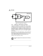
Connection of a floating signal source to the USB-2401 in
differential input mode is as shown.
Figure 3-3: Floating Source and Differential Input
3.3.2
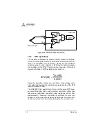
Current Input Mode
Current signal source can be floating or grounded reference,
converted to voltage through a precision 249.5
resistor.
Cross-voltage on the precision resistor is considered differential
signal. The differential signal pair passes through differential
amplifier buffers and is measured by the analog-to-digital
converter chip (ADC) with ±2.5 V input range.
The formula to calculate voltage-to-current conversion is:
AI-
AI+
Floating signal source
GND
Amplifier
Amplifier
USB-2401
6701527
.
18
)
(
)
(
volt
V
mA
Current
=
Summary of Contents for USB-2401
Page 8: ...viii List of Figures This page intentionally left blank...
Page 10: ...x List of Tables This page intentionally left blank...
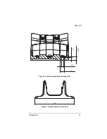
Page 22: ...12 Introduction Figure 1 3 USB 2401 Module Side View...
Page 23: ...Introduction 13 USB 2401 Figure 1 4 USB 2401 Module Front View 41 3 114...
Page 25: ...Introduction 15 USB 2401 Figure 1 7 Module In Stand Front View...
Page 26: ...16 Introduction Figure 1 8 Module Stand Top View 20 4 20 4 B 26...
Page 30: ...20 Introduction This page intentionally left blank...
Page 34: ...24 Getting Started Figure 2 4 Module Pre Rail Mounting Figure 2 5 Module Rail Mounted...
Page 36: ...26 Getting Started This page intentionally left blank...
Page 56: ...46 Calibration This page intentionally left blank...


