26
Connectors & Jumpers
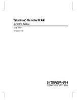
JP1 - System Panel Connector
Figure 2-15: JP1 and Pin Assignments
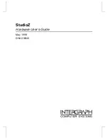
SATA1 & SATA2 - Serial-ATA Ports
Figure 2-16: SATA Connectors and Pin Assignments
PIN # SIGNAL NAME PIN # SIGNAL NAME
1 5V 11
Buzzer
2 NA 12
N/A
3 POWER
LED
13
N/A
4 NA 14
5V
5 GND 15
RESET
6 GND 16
GND
7 NA 17
HDD
LED
8 PS
ON 18
5V
9 5VSB 19
POWER
BTW
10
PME 20
GND
PIN
SIGNAL
FUNCTION
1 GND
Ground
2 SATA_TXP
3 SATA_TXN
Serial ATA Transmit
Pair
4 GND
Ground
5 SATA_RXN
6 SATA_RXP
Serial ATA Receive
Pair
7 GND
Ground
1
7
Summary of Contents for NuPRO-720
Page 6: ...vi Preface This page intentionally left blank ...
Page 10: ...x List of Figures This page intentionally left blank ...
Page 12: ...xii List of Tables This page intentionally left blank ...
Page 26: ...14 Introduction 1 9 Board Layout Figure 1 2 NuPRO 720 Board Layout ...
Page 28: ...16 Introduction This page intentionally left blank ...
Page 58: ...46 Getting Started This page intentionally left blank ...
Page 62: ...50 Watch Dog Timer This page intentionally left blank ...
Page 84: ...72 BIOS Setup ...