


Registers Format
•
17
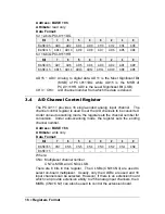
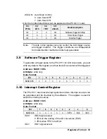
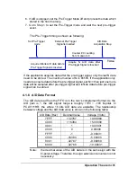
3.5 A/D Channel Read Back Register
The AD channel setting can be read back from this register.
Address: BASE + 6h
Attribute:
read only
Data Format:
Bit
7
6
5
4
3
2
1
0
BASE+6h
AS3
AS2
AS1
AS0
CN3
CN2
CN1
CN0
BASE+7h
--
--
--
--
--
--
--
--
Where:
CNn: channel number
ASn: Auto scan channel number.
There are 8 bits in this register. Under non-auto scan mode, the 4 LSBs
(CN0~CN3) show the channel number setting and the 4 MSBs (AS3~AS0)
is all ‘0’. Under auto-scan mode, the 4LSBs record the ending channel
number. The 4 MSBs is the selected channel, and the value will increase
automatically if any A/D trigger signal is inserted.
3.6 A/D Input Signal Range Control Register
The A/D range register is used to adjust the analog input ranges. This
register directly controls the PGA (programmable gain amplifier). When a
different gain value is set, the analog input range will be changed to the its
corresponding value.
Address: BASE + 8h
Attribute:
write only
Data Format:
Bit
7
6
5
4
3
2
1
0
BASE+8h
X
X
X
X
X
G2
G1
G0
BASE+9h
X
X
X
X
X
X
X
X
The relationship between gain setting and its corresponding A/D range is
listed in the table below.
G2
G1
G0 GAIN
Analog Input Range
Gain Code used in
Software Library
0
0
0
1
±
10V
AD_B_10_V
0
0
1
2
±
5V
AD_B_5_v
0
1
0
4
±
2.5V
AD_B_2_5_V
0
1
1
8
±
1.25V
AD_B_1_25_v
1
0
0
16
±
0.625V
AD_B_0_625_V
Summary of Contents for NuDAQ PCI-9111DG
Page 1: ...NuDAQ PCI 9111DG HR Multi Functions Data Acquisition Card User s Guide ...
Page 4: ......
Page 10: ......


