24
Leading
EDGE COMPUTING
3.5
Mounting
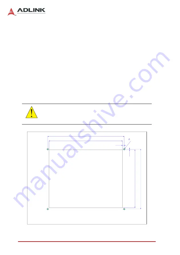
The DMI-1210 can be panel mounted using 4 countersunk M5
screws and O-rings. Make sure there is adequate space behind
the panel for ventilation and I/O connectors, and that the panel
material and thickness can support the weight of the device.
1. Prepare the panel opening and screw holes as shown in
the Figure 3-1 below (M5 thread or
Φ
5.5 through hole).
2. Attach I/O cables to the device before installing into the
panel if rear access will be limited after installation (see
“Mechanical Layout” on page 8.).
3. Place the device into the panel cutout and secure with 4
countersunk M5xL40 screws and O-rings provided as
shown in Figure 3-2 (torque: 10.0 Kgf-cm).
Figure 3-1: DMI-1210 Mounting Hole Locations
CAUTION:
Do not overtighten the screws to prevent damaging the rubber
seal on the back of the bezel.
286
224
274.50
216.90
6.50
2.18
M5 Thread x4
5.5 through hole)
(or
Summary of Contents for DMI-1210
Page 8: ...viii Table of Contents Leading EDGE COMPUTING This page intentionally left blank...
Page 10: ...x List of Figures Leading EDGE COMPUTING This page intentionally left blank...
Page 12: ...xii List of Tables Leading EDGE COMPUTING This page intentionally left blank...
Page 16: ...4 Leading EDGE COMPUTING This page intentionally left blank...
Page 26: ...14 Leading EDGE COMPUTING This page intentionally left blank...
Page 31: ...19 DMI 1210 2 Install the PC 104 MVB module with four M3 screws as shown MVB Module M3 Screws...
Page 43: ...31 DMI 1210 11 Wi Fi To install the Wi Fi driver do the following Open the Device Manager...
Page 45: ...33 DMI 1210 Select Browse my computer for driver softwaret...
Page 51: ...39 DMI 1210 Wi Fi will now be functional...
Page 66: ...54 Leading EDGE COMPUTING This page intentionally left blank...


