


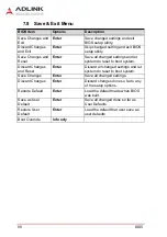

BIOS
85
DMI-1040
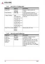
7.5
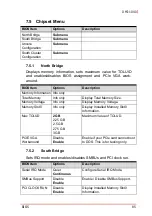
Chipset Menu
7.5.1
North Bridge
Displays memory information, sets maximum value for TOLUID
and enables/disables BIOS assignment and PCIe VGA work-
around.
7.5.2
South Bridge
Sets IRQ mode and enables/disables SMBUs and PCI clock run.
BIOS Item
Options
Description
North Bridge
Submenu
South Bridge
Submenu
Uncore
Configuration
Submenu
South Cluster
Configuration
Submenu
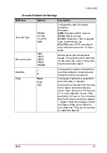
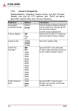
BIOS Item
Options
Description
Memory Information Info only
Total Memory
Info only
Display Total Memory Size.
Memory Voltage
Info only
Display Memory Voltage.
Memory Slot0
Info only
Display Installed Memory Slot0
Information.
Max TOLUD
2 GB
2.25 GB
2.5 GB
2.75 GB
3 GB
Maximum Value of TOLUD.
PCIE VGA
Workaround
Disable
Enable
Enable if your PCIe card cannot boot
to DOS. This is for testing only.
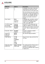
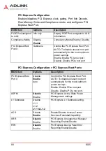
BIOS Item
Options
Description
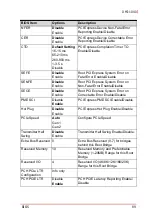
Serial IRQ Mode
Quiet
Continuous
Configure Serial IRQ Mode.
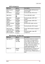
SMBus Support
Disable
Enable
Enable / Disable SMBus Support.
PCI CLOCK RUN
Disable
Enable
Display Installed Memory Slot0
Information.
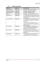
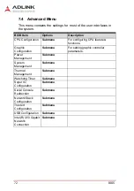
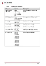
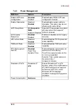
Summary of Contents for DMI-1040
Page 8: ...viii Table of Contents This page intentionally left blank...
Page 10: ...x List of Figures This page intentionally left blank...
Page 12: ...xii List of Tables This page intentionally left blank...
Page 27: ...Getting Started 15 DMI 1040 6 Disconnect the cable connecting the speakers to the main board...
Page 40: ...28 Getting Started This page intentionally left blank...
Page 45: ...Driver Installation 33 DMI 1040 Click Next The system will begin installing the Wi Fi driver...
Page 66: ...54 Driver Installation This page intentionally left blank...


