background image

Table of Contents 

 i 

Table of Contents


Chapter 1 Introduction............................................................. 1


1.1


About the Serial Communication Modules .............................1


1.2


Overview of cPCI-3534 ........................................................2


1.2.1


What is cPCI-3534?.....................................................................2


1.2.2


Feature of cPCI-3534..................................................................2


1.2.3


Specification of cPCI-3534 .........................................................3


1.2.4


Connector Pin Assignment of cPCI-3534 ................................4


1.3


Overview of cPCI-3544 ........................................................8


1.3.1


What is cPCI-3544?.....................................................................8


1.3.2


Feature of cPCI-3544..................................................................8


1.3.3


Specification of cPCI-3544 .........................................................9


1.3.4


Connector Pin Assignment of cPCI-3544 ..............................11


1.4


Overview of cPCI-3538 ...................................................... 14


1.4.1


What is cPCI-3538?...................................................................14


1.4.2


Feature of cPCI-3538................................................................14


1.4.3


Specification of cPCI-3538 .......................................................15


1.4.4


Connector Pin Assignment of cPCI-3538 ..............................17


Chapter 2 Installation .............................................................20


2.1


What You Have ................................................................. 20


2.2


Unpacking......................................................................... 21


2.3


Installation Procedure ........................................................ 22


2.4


Hardware Configuration ..................................................... 23


2.4.1


Wiring Example..........................................................................23


2.5


Software Installation .......................................................... 24


2.5.1


Windows NT Installation...........................................................24


2.5.2


Windows 95/98 Installation.......................................................26


2.5.3


For UNIX, LINUX and QNX user.............................................27


2.5.4


Windows 95/98/NT Utility Diagram for cPCI-3544................28


2.6


AP Examples .................................................................... 30


2.6.1


Dos Environment........................................................................30


2.6.2


Windows(Windows 95/98/NT) Environment..........................30


2.6.3


Linux Environment.....................................................................30


Product Warranty/Service.....................................................31


Artisan Technology Group - Quality Instrumentation ... Guaranteed | (888) 88-SOURCE | www.artisantg.com

Summary of Contents for cPCI-3534

Page 1: ...ss underutilized and idle equipment along with credit for buybacks and trade ins Custom engineering so your equipment works exactly as you specify Critical and expedited services Leasing Rentals Demos...

Page 2: ...cPCI 3534 cPCI 3544 cPCI 3538 4 8 Ports Serial Communication Modules User s Guide Recycled Paper Artisan Technology Group Quality Instrumentation Guaranteed 888 88 SOURCE www artisantg com...

Page 3: ...Artisan Technology Group Quality Instrumentation Guaranteed 888 88 SOURCE www artisantg com...

Page 4: ...damages This document contains proprietary information protected by copyright All rights are reserved No part of this manual may be reproduced by any mechanical electronic or other means in any form w...

Page 5: ...link com tw AMB amb adlink com tw TEL 886 2 82265877 FAX 886 2 82265717 Address 9F No 166 Jian Yi Road Chungho City Taipei 235 Taiwan R O C Please inform us of your detailed information for a prompt s...

Page 6: ...T LINUX SCO Open Server External connector Four DB25 male cable connector or DB9 male connector Four DB25 male cable connector or DB9 male connector Eight DB25 male cable connector or DB9 connector Re...

Page 7: ...Artisan Technology Group Quality Instrumentation Guaranteed 888 88 SOURCE www artisantg com...

Page 8: ...4 1 4 2 Feature of cPCI 3538 14 1 4 3 Specification of cPCI 3538 15 1 4 4 Connector Pin Assignment of cPCI 3538 17 Chapter 2 Installation 20 2 1 What You Have 20 2 2 Unpacking 21 2 3 Installation Proc...

Page 9: ...Artisan Technology Group Quality Instrumentation Guaranteed 888 88 SOURCE www artisantg com...

Page 10: ...r will overrun and data lost The serial communication interface series can support buffer capability or local processor and dual port RAM in each port s transmit and receive channel simultaneously Thi...

Page 11: ...I 3534 interface card The R 3534 transition board can support rear IO connection by using one DB37 connector 1 2 2 Feature of cPCI 3534 32 bit CompactPCI 3U form factor PCI Rev 2 1 Plug and Play IRQ a...

Page 12: ...ndent RS 232C compatible ports 1 isolated RS 422 485 port DIP switch select Max port per system 8 2 card Isolation voltage 2500VDC Baud rate Each port can be configured to 50 115 200 bps Operation Sys...

Page 13: ...l Name 1 RXD1 IN 20 TXD1 OUT 2 CTS1 IN 21 RTS1 OUT 3 DSR1 IN 22 DTR1 OUT 4 DCD1 IN 23 RI1 IN 5 GND 24 RXD2 IN 6 TXD2 OUT 25 CTS2 IN 7 RTS2 OUT 26 DSR2 IN 8 DTR2 OUT 27 DCD2 IN 9 GND 28 RI2 IN 10 29 RI...

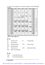
Page 14: ...IN 4 485TRXD I O 5 485TRXD I O 6 422RXD IN 7 GND 20 422TXD OUT DB9 male connector pin assignment in cPCI 3534 module for RS 232 interface port A B and C DB9 Pin No Signal Name 2 TXD OUT 3 RXD IN 4 RT...

Page 15: ...D DSR SG DCD DTR GND 7 GND FG TX RX RTS CTS GND 6 GND GND 5 GND GND 4 GND DSR SG DCD DTR GND 3 GND FG TX RX RTS CTS GND 2 GND GND 1 GND GND Pin Z A B C D E F P2 J2 C O N N E C T O R Port A Port B Port...

Page 16: ...s a rear I O connection transition the connector and cable used in the rear is the same as the front DIP Switch and Jumper Setting SW1 ON OFF SW1 1 Card1 Card2 SW1 4 RS 422 RS 485 The JP1 is for the R...

Page 17: ...h cPCI 3544 interface card The R 3544 transition board can support rear IO connection by using one DB37 connector 1 3 2 Feature of cPCI 3544 32 bit CompactPCI 3U form factor PCI Rev 2 1 Plug and Play...

Page 18: ...4 isolated RS 422 485 port DIP switch software select Max port per system 32 8 card Isolation voltage 500VDC Baud rate Each port can be configured to 50 115 200 bps Operation System Compatibility Wind...

Page 19: ...e temperature 20 65 C Humidity 10 95 non condensing Dimension 160 x 100 mm 2 6 3 x 3 9 in 2 3U Power consumption 5V 1400mA typical Artisan Technology Group Quality Instrumentation Guaranteed 888 88 SO...

Page 20: ...D3 OUT 31 422_RXDC IN 13 32 485_D3 I O 14 422_TXD3 OUT 33 422_RXD3 IN 15 GND4 34 16 485_D4 I O 35 422_TXD4 OUT 17 422_RXD4 IN 36 18 485_D4 I O 37 422_TXD4 OUT 19 422RXD4 IN DB25 male connector pin ass...

Page 21: ...ND GND 10 GND GND 9 GND TXD TXD GND 8 GND GND D RXD D RXD GND 7 GND GND 6 GND GND 5 GND GND 4 GND TXD TXD GND 3 GND GND D RXD D RXD GND 2 GND GND 1 GND GND Pin Z A B C D E F P2 J2 C O N N E C T O R Po...

Page 22: ...etting CARD NO Port Select SW1 3 PortA PortB PortC PortD 000 0 SW On Off On Off On Off On Off 100 1 4 485 422 010 2 5 485 422 110 3 6 485 422 001 4 7 485 422 101 5 011 6 111 7 The JP1 JP3 JP5 JP7 is f...

Page 23: ...C588XB for providing 8 channel isolated RS 232 422 485 interface The R 3538 transition board can support rear IO connection by using one DB62 connector 1 4 2 Feature of cPCI 3538 32 bit CompactPCI 3U...

Page 24: ...nt RS 232C compatible ports Optional external C588XB box for extending to 8 isolated RS 232 422 485 port Max port per system 16 2 card Baud rate Each port can be configured to 50 115 200 bps Operation...

Page 25: ...e temperature 20 65 C Humidity 10 95 non condensing Dimension 160 x 100 mm 2 6 3 x 3 9 in 2 3U Power consumption 5V 1400mA typical Artisan Technology Group Quality Instrumentation Guaranteed 888 88 SO...

Page 26: ...4 OUT 10 RTS3 OUT 31 RTS7 OUT 52 DCD4 IN 11 CTS3 IN 32 CTS7 IN 53 TXD8 OUT 12 DSR3 IN 33 DSR7 IN 54 RXD8 IN 13 DTR3 OUT 34 DTR7 OUT 55 RTS8 OUT 14 DCD3 IN 35 DCD7 IN 56 CTS8 IN 15 TXD5 OUT 36 TXD6 OUT...

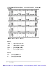
Page 27: ...SG GND 18 GND FG TX RX SG GND 17 GND DSR DCD DTR RTS CTS GND 16 GND GND 15 GND DSR DCD DTR RTS CTS GND 14 GND FG TX RX SG GND 13 GND FG TX RX SG GND 12 GND DSR DCD DTR RTS CTS GND 11 GND GND 10 GND D...

Page 28: ...G Signal Ground DCD Data Carrier Detect DTR Data Terminal Ready R 3538 Rear IO Daughter Board The R 3538 rear I O daughter board provides a rear I O connection transition the connector and cable used...

Page 29: ...er s Manual the package includes the following items cPCI 3534 3544 3538 Serial Communication Interface Module Expansion Cable C425M C409M or C825M C809M R 3534 3538 Rear IO Daughter Board For the rea...

Page 30: ...e to your module Be sure there are no shipping and handing damages on the module before processing After opening the module carton extract the system module and place it only on a grounded anti static...

Page 31: ...ot 4 Before handling the serial communication module discharge any static buildup on your body by touching the metal case of the computer Hold the edge and do not touch the components 5 Position the m...

Page 32: ...CI 3534 and the JP1 for cPCI 3538 is used for the system to recognize the first or second card of the same model in the system if there are two cards of the same on board The SW1 3 for cPCI 3544 is us...

Page 33: ...ufacturer 4 When prompted for the path specify the drive and directory where the NCPA can find the new driver for the card you install For cPCI 3534 we may specify as follow X NuCOM CPCI3534 NT4 For c...

Page 34: ...eously we can not confirm that both cards will active properly 7 If you install multiple cards in one NT system simultaneously please confirm that the COM port number assigned do not overlap for diffe...

Page 35: ...u must confirm to let one card s switch is ON and the other card s switch is OFF 3 The card with switch ON will have COM port number assigned for first card The card with switch OFF will have COM port...

Page 36: ...ight have wrong operation 2 5 3 For UNIX LINUX and QNX user You can download the tar driver from ADLINK website or contact the dealer near you for service and support Artisan Technology Group Quality...

Page 37: ...S 422 485 serial communication module It supports the software configuration for RS 422 485 When choosing the RS 422 mode the RS 485 port would be disabled automatically You can run the AdlComSet exe...

Page 38: ...maps to system port Port mode When checked the configuration will be true after rebooting If it was not checked after rebooting the port mode will follow the DIP switch configuration Artisan Technolo...

Page 39: ...ler from whom you purchase the product or the service mailbox in ADLink 2 6 2 Windows Windows 95 98 NT Environment You can find the extra ports in the system control panel after installing the driver...

Page 40: ...s specifications or if the serial number has been removed ADLINK does not assume any liability for consequential damages as a result from our product uses and in any event our liability shall not exce...

Page 41: ...uipment Have surplus equipment taking up shelf space We ll give it a new home Learn more Visit us at artisantg com for more info on price quotes drivers technical specifications manuals and documentat...

Reviews: