Operation and Maintenance
17
2.
The LEDs on the left front panel of the drive will turn ON at the same time for about three seconds and
then turn OFF.
3.
The
Operate Handle
,
Write Protected
, and
Use Cleaning Tape
LEDs will turn OFF. The
Tape
in Use
LED will blink while the tape drive initializes.
4
If your external SCSI bus terminator(s) have a Term Power LED it should also be illuminated.
Drive Status
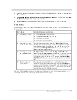
After completion of the drive POST and initialization, each drive will be in one of the four states listed in the
following table:
Drive State
Indicator Displays and Actions
1.
No cartridge is present
A.
The
Tape in Use
LED turns OFF.
B.
The
Operate Handle
LED turns ON.
C.
The handle is unlatched.
D.
The drive beeps momentarily.
2.
A cartridge is present
and the handle is closed.
The drive loads the cartridge. When the
Tape in Use
LED stops
blinking and stays ON, the tape’s actual density lights. For example, if
the actual tape density is 2.6, then the LED turns ON next to the 2.6
label. When the
Density Override
LED blinks, you can select a
density. The drive is ready for use.
3.
A cartridge is present,
but the handle is open.
The
Tape in Use
LED turns OFF. The
Operate Handle
LED
flashes. When the
Tape in Use
LED stops blinking and stays ON, the
tape’s actual density lights. For example, if the actual tape density is
2.6, then the LED turns ON next to the 2.6 label. When the
Density
Override
LED blinks, you can select a density. The drive is ready for
use.
4.
The drive detects an
error condition.
Then all right or left side LEDs blink repeatedly. You may try to
unload the tape and reinitialize the drive by pressing the
Unload
key
or turn power OFF and then ON again. The right or left side LEDs stop
blinking and the drive tries to reinitialize. The LEDs turn ON steadily
again and then turn OFF if the test succeeds.
The drive POST completes in about 13 seconds on each drive, and the drives will respond normally to all
commands. However, it may take longer for the media to become ready.
Summary of Contents for Tape Array 5
Page 1: ...Installation and O perating Guide Tape Array 5 Rackmount Enclosure...
Page 8: ...viii Blank Page...
Page 10: ...x Table of Contents Blank Page...
Page 16: ...6 Introduction Blank Page...
Page 24: ...14 Installation Blank Page...
Page 25: ...15 Chapter 3 Operation and Maintenance This Chapter p explains how to operate the T5 Enclosure...
Page 40: ...30 Operation and Maintenance Blank Page...
Page 44: ...34 Troubleshooting and Diagnostics Blank Page...
Page 45: ...35 Appendix A Specifications This Appendix p contains specification information on the T5...


