


53
SECTION VIII
SYSTEM PARAMETER/PROGRAM LOCATION CHART
MLC = Manually Loaded Cycles
PPC = Preprogrammed Cycles
* Reversing Models ONLY
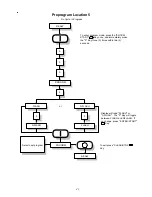
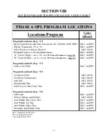
PHASE 6 OPL PROGRAM LOCATIONS
Locations/Programs
Cycles
Affected
Program Location 2 (Key “2”)
Dryer Operation Specific Heat Selection (GAS, STEAM, ELECTRIC)
Display Temperature (ºF or ºC)
Select Reverse or Always Reverse*
Rotational Sensor or No Rotational Sensor
“A” Factor (Slope) -
refer to
“A”
and
“B” Factor Parameters
on
page 56
“B” Factor (Offset) -
refer to
“A”
and
“B” Factor Parameters
on
page 56
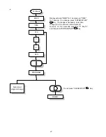
Program Location 5 (Key “5”)
Flash or No Flash
Program Location 8 (Key “8”)
Cool Down Time
Cool Down Temperature
Spin Time
Stop (Dwell) Time
End-Of-Cycle Buz (Tone) Time
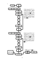
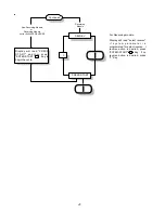
Program Location 0 (Key “0”)
Lint Count
With or Without Anti-Wrinkle
Anti-Wrinkle Buz (Tone) Time
Anti-Wrinkle On Time
Anti-Wrinkle Delay Time
Maximum Anti-Wrinkle Time
MLC and PPC
MLC and PPC
MLC ONLY
MLC and PPC
MLC and PPC
MLC and PPC
MLC and PPC
MLC ONLY
MLC ONLY
MLC ONLY
MLC ONLY
MLC and PPC
MLC and PPC
MLC ONLY
MLC and PPC
MLC and PPC
MLC and PPC
MLC and PPC