USER’S MANUAL
V-line 899x.xxx/LPG HYBRID
Enclosure No. 12
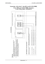
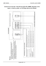
Conditions of wiring and operation of UPS for feeding a control system
and electronic part of V–line dispensers
1.
All the cooperating electronic circuits of the control system and dispensers must be
connected to the UPS and for this point of view they are considered as a closed electronic
unit.
2.
The control system and electronic instruments of dispensers connected to it as a closed
electronic unit must be connected only to one source of UPS.
3.
The feeding of perhaps even a part of the system from another source is not permitted.
4.
A parallel cooperation of more UPS on one system is not permitted.
5.
"Live" conductors of control system supply circuits and dispenser electronic equipment must
be galvanic-separated from the mains and even from protective conductors – a system of
"swimming zero" is created.
6.
To comply with the requirement under item 5, the proper UPS must have galvanic-separated
input and output circuits.
7.
For feeding of electronic system of the filling station, the UPS of ON LINE type must be used
exclusively.
8.
For the correct function of UPS, the size of permanently installed load representing max. 60
% of nominal UPS output, must be provided.
9.
To the stabilized voltage circuits, no other consumers that are not a part of prescribed
technology, can be connected.
10.
Therefore the sockets of stabilized voltage must be marked by the description e.g. "Control
system feeding".
11.
The protection of input circuits of UPS must be dimensioned so that UPS feed outage and
total battery discharge did not occur under standard equipment function.
Operating conditions of the V-line 899x.xxx/P fuel dispensers
(pressure design)
The pressure system of the distribution should be designed with a submerged pump built-in
directly into the storage tank under the substance level. The tank should be equipped with a
detector of the lowest substance level switching the el. circuit of the pump motor being the
min. level attained.
The location of the pump under the lowest fluid level in the storage tank and the min. level
control switch shall prevent the access of air or gas into the pump.
P12 = 0 parameter shall be preselected in the electronic counter for the pressure system of
submerged pumps operation in the storage tank in case of V-line 899x.xxx/P dispensers
operation. At first the electronic counter starts up the submerged pump in this mode of
operation (the fluid in entire hydraulic system is under pressure) then the counter tests the
displays and closes the el. magnetic valve - and the dispensing is started.

