background image

CALIBRATION OF THE MECHANICAL LITRE COUNTER (AF3000)

Calibration is necessary when the litre counter is new, after dismounting, when a different 

fluid is measured or as consequence of significant wear. Calibration of the litre counter can be 

changed easily by following the calibration procedure listed below. For the calibration proce-

dure it is necessary a test container or a container of KNOWN volume. It is recommended that 

the container has a volume of at least 19 litres (5 gallons).

calibration procedure 

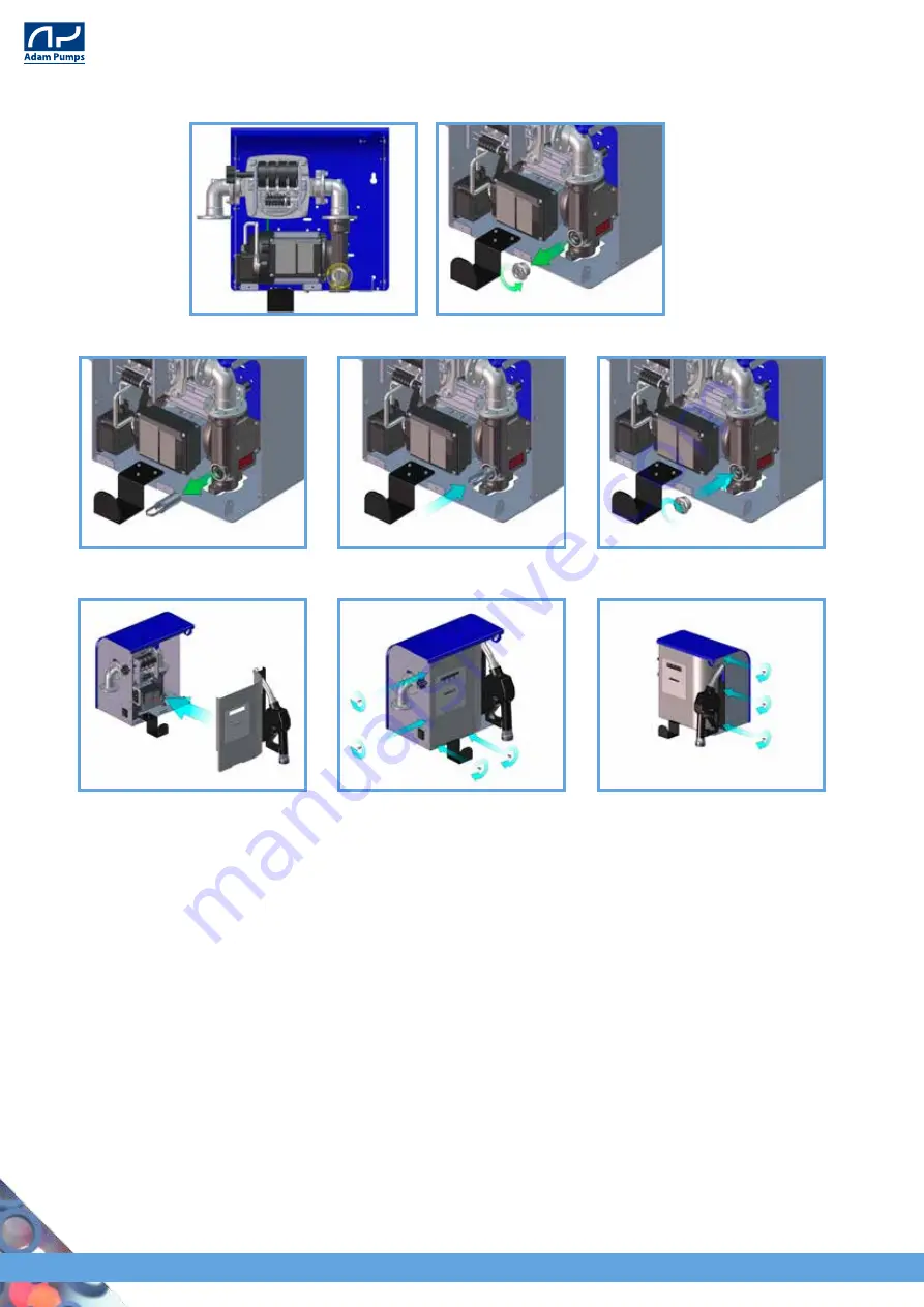
  1. Follow Figures  

1-3


(as for clearing of the filter, page 41) to access to the calibration screw;

  2. Fill the container up to a known volume;

  3. if the indicated quantity does not correspond to the known volume, the litre counter must

  be calibrated. Make sure that the pump is closed and that the pressure is interrupted, hence

  remove the sealing screws and rotate the calibration screw (Fig. A) in the anticlockwise 

  direction to reduce the indicated quantity, or in the clockwise direction to increase this

  quantity. A full rotation changes the indicated quantity by about 0.4 of a litre. Reinstall the

  sealing screw;

4. repeat point 2 until the calibration is acceptable.

2. identify the filter to be cleaned in the lower part on the right of the pump and unscrew the 

plug;

3. extract the filter, clean it and screw back its plug;

4. replace in the original position the front metal sheet and screw back all seven screws.

42

AF 3000 - AF 3000 TAG

Summary of Contents for AF 3000

Page 1: ...USE AND MAINTENANCE INSTRUCTIONS MANUAL Machine FUEL DISTRIBUTOR PUMP Model AF 3000 AF 3000 TAG ORIGINAL INSTRUCTIONS AF 3000 AF 3000 TAG WWW ADAMPUMPS COM ...

Page 2: ... 0 0 0 0 0 0 0 0 REVISION DATE 0 0 0 0 0 0 0 0 0 0 0 0 0 0 0 0 0 0 0 0 0 0 it is the customer s responsibility to make sure that in the event that this document undergoes modifications by the manufacturer only the updated versions of the manual are actually present in the points of use THE ITALIAN LANGUAGE IS THE OFFICIAL LANGUAGE CHOSEN BY THE MANUFACTURER no liabilities are assumed for translati...

Page 3: ...ORT AND HANDLING 16 2 CONNECTIONS 17 3 PRELIMINARY CONTROL 17 4 DESCRIPTION OF THE MACHINE 18 1 PRELIMINARY CONTROL 18 2 PRINCIPLE OF OPERATION 18 3 MAIN COMPONENTS 19 4 ELECTROMAGNETIC ENVIRONMENT 20 5 DIGITALVERSION OPERATION 21 5 OPERATION PROBLEMS 38 6 MAINTENANCE 40 1 STATE OF MAINTENANCE 40 2 ISOLATION OF THE MACHINE 40 3 PROGRAMMED ROUTINE MAINTENANCE 40 4 EXTRAORDINARY MAINTENANCE 41 7 ACC...

Page 4: ...ors and maintenance workers of the machine in depth knowledge of the planned not planned and not permitted uses correct use under safety conditions carrying out maintenance and repairs actions correctly and safely technical assistance and the management of the spare parts disposal of waste products from the machine decommissioning of the machine under safety conditions and in compliance of the urr...

Page 5: ...anslations not approved by the latter therefore if incongruence is de tected attention must be paid to the original language and eventually contact the commercial office of the Manufacturer who will make the changes deemed appropriate The Manufacturer reserves the right to introduce changes to the project variations impro vements to the machine and updates to the Instructions Manual without prior ...

Page 6: ...f distribution or use COMMISSIONING First use in compliance with its intended use within the European Com munity of a machine object of this Directive SAFETY COMPONENT Component intended to fulfil a safety operation placed on the market separately the failure and or malfunction of which endangers the safety of persons and which is not essential for the purpose for which the machine has been design...

Page 7: ...he safety pictographs are regularly checked and cleaned to ensure their good readability at a safe distance When the products are subjected to extreme environmental conditions or anyhow when the safety pictographs do not meet any longer the required visibi lity conditions they must be substituted REPAIRS Element of the machine used specifically to guarantee the protection through a material barrie...

Page 8: ...GRAPHS PICTOGRAPHS RELATED TO DANGERS PICTOGRAPHS RELATED TO OBLIGATIONS SYMBOL DESCRIPTION General danger Electrical current SYMBOL DESCRIPTION It is mandatory to wear protection gloves 8 AF 3000 AF 3000 TAG ...

Page 9: ...n in an indelible way its reference data The position of the plate on the machine may vary from machine to machine For any communication with the Manufacturer or the assistance centres give always these references ADAM PUMPS Spa Via della Resistenza 48 41011 Campogalliano Modena Italy 2006 NOV Code AF3600420 DISTRIB AF3000 70L 230 Volt 50 Hz imb Serial Number 180387 230 Volt 50 Hz IP 55 370W 2 5 A...

Page 10: ... ap proximation of the legislations of the Member States relating the electromagnetic compatibility Directive 2006 95 EC of the European Parliament and Council of 12 December 2006 concerning the approxi mation of the legislations of the Member States relating the electrical material intended to be used within certain voltage limits AND AUTHORISED 3 STATEMENTS ADAM PUMPS S p A Company Via della Res...

Page 11: ...licit written authori sation by the Manufacturer invalidate the guarantee and relieve the Manufacturer from any liability for damage caused from faulty product This is valid in particular when the above mentioned changes are carried out on the safety devices by degrading their efficiency The same considerations apply when not original spare parts are used or different from those explicitly indicat...

Page 12: ...arantee remains excluded in the event that the product is in spected or mishandled by persons bodies and companies outside of the adam pumps s p a circuit each guarantee request is subject to the approval of adam pumps an authorisation code is requested for the return of the goods this code will be provided by adam pumps at the request of the customer who will invoke the guarantee on the product t...

Page 13: ...ollowing indications It is absolutely prohibited to inhibit the safety measures installed on the machine Do not modify for any reason parts of the machine in the event of malfunction due to absence in meeting the above the Manufacturer is not liable of the consequences It is recommended to request possible changes directly from the Manufacturer Place the machine according with the diagrams provide...

Page 14: ...ts CONTROLS AND CHECKS Checking must be carried out by an expert person they must be of the visual and functional type with the purpose of guaranteeing safety of the machine They include checking of all the safeties installed on the machine functional checking of the machine checking of the state of the machine In order to guarantee maximum safety of the machine it is anyhow FORBIDDEN to mishandle...

Page 15: ...uids and corro sive flammables and food liquids The machine is not designed for use in an explosive atmosphere Entrusting the use of the pump to children or handicapped persons is prohibited Use of the pump in closed environments in the presence of vehicles using petrol GPL or methane is prohibited It is necessary to pay attention to the following residual risks which are present when using the ma...

Page 16: ... sufficiently aired and lighted For a better use it is recommended to anchor the group as close as possible at the level of the liquid to be pumped max 2 m height above the level of the liquid 5 Screw the distribution pipe on the flange of the litre counter and on the NOZZLE 6 We recommend to use the ADAM PUMPS suction pipe alternatively use exclusively a rub ber or plastic suction pipe resistant ...

Page 17: ...equipped with a 30mA minimum life saving protection ac cording to the DIN Standards The plug must be connected to a current socket suitable for a SHUKO socket with earthing contact It is prohibited to cut or substitute the plug supplied as standard 17 AF 3000 AF 3000 TAG ...

Page 18: ...t is possible to proceed with starting the operation After having inserted the suction pipe in the tanker and the NOZZLE in the special filling hole switch on the pump release gradually the NOZZLE lever and start the transfer of the diesel oil When filling is completed release control of the NOZZLE and switch off the switch When the pump is not used discon nect the plug In the event that an automa...

Page 19: ...bution pipe support bracket 6 on off general switch MANUFACTURING CHARACTERISTICS OF THE MOTOR Self ventilated closed electrical motor with IP 55 protection insulation class F MANUFACTURING CHARACTERISTICS OF THE PUMP Pump body G 25 CAST IRON Motor support ALUMINIUM Impeller SYNTERED IRON Motor shaft C 40 STEEL Reducer ALUMINIUM 1 6 2 3 4 5 19 AF 3000 AF 3000 TAG ...

Page 20: ...nments SYMBOLS FUNCTIONALITY Software is divided in 2 modes USER can ben navigated using the and buttons by anybody and this without any ac cess key or TAG It allows to visualize the total per authorized user and see blocked users as well as the PERIOD TOTAL and GENERAL TOTAL MASTER only accessible with the MASTER card this mode allows full control of device s functions allows setup of TAG Users m...

Page 21: ... It will also be necessary to program the user TAG keys to authorize refuelling see dedicated paragraphs Remove the transparent protection on meter display MASTER FUNCTIONS Starting from partial screen proceed with to enter in MASTER mode Approaching the MASTER card the systems sounds Beep 3 times and the screen Prog appears In this mode button allows to go to next function while button confirms t...

Page 22: ...OWNLOAD DATA sold separately is resetting all PERIOD totals To cancel period totals do as follows 1 enter in master mode 2 to confirm 3 to select YES or NO 4 to confirm the display shows ok to confirm cancellation To exit wait 60 secondi or press several times to display EXIT then confirm with SCREEN CANCEL TOTALS MESSAGE CLRTOT SCREEN TRANSACTION PRESELECTION MESSAGE PRESET ATTENTION condition is...

Page 23: ...s function permits to set a maximum of units that this user TAG can transfer during a manager defined period It is important to know that the PERIOD is defined by the manager and is the time betwen CANCEL TOTALS procedure or the download of data with the KIT DOWNLOAD DATA sold separately Press R to enter in this function Press until the desired maximum quantity is on the display increments the val...

Page 24: ...confirm save Once the transaction preselection preset and the period preselection pre per are set for the user TAG key s proceed as follows 1 Press to enter in this function 2 Press to select the TAG to program 3 Press to confirm 4 Approach the user TAG for programming beep sound and display OK are confir ming the good programming of the key 5 Repeat the operations above for all keys to be program...

Page 25: ...n be configured as follows 1 Enter in UNIT OF MEASURE mode 2 Confirm the unit of measure custom with buton the meter will propose the default value blinking 0 100 To obtain such a coefficient it will be necessary to simply divide cu stom litre Example if we desire to have a custom unit 1 00 for a 0 33 litre can we have to divide 1 0 33 3 03 and insert the new coefficient 3 03 3 Increase or decreas...

Page 26: ...alibration procedure 1 Starting from Partial screen approach a user TAG and refill a calibration jug to a known volume it is important to do this at a flow rate of minimum 10 litres a minute without top ping up else calibration could be inaccurate Use the nozzle fully open 2 if the displayed quantity is not matching the measured quantity the meter must be calibra ted 3 to enter in calibration mode...

Page 27: ...to increment the value pressing button this is a loop keep button being only used to confirm the modified value reset partial screen while approaching TAG only reset partial screen while pressing R button not used not used double horizontal Reed switch reading vibrations elimination and flow direction control not useable single horizontal Reed switch not recommended minimum pulse count to consider...

Page 28: ...e done starting from USER mode press simultane ously for 2 seconds With this procedure nothing will be erased USER FUNCTIONS The system if left untouched or if not receiving any pulses for at least 60 seconds automatical ly goes back to Partial screen i e USER mode screen from which transactions are initiated This mode can be accessed by anyone even without and TAG or card Each time button is pres...

Page 29: ...lays 4 2 digits any transaction will always start from that screen Independently of the screen currently displayed after 10 seconds without activity in USER mode or 60 in MA STER mode the system automatically return to that starting screen This screen is used as initial condition to describe other 4 available screens TOTAL SCREEN MESSAGE TOTAL LITRES 29 AF 3000 AF 3000 TAG ...

Page 30: ... SCREEN WITH MESSAGE TOTPER displays 5 1 digits shows all litres transferred in the defined period of time since the last download of data or last cancellation of totals This totalizer can only be reset by the MASTER see paragraph cancel total screen SCREEN PERIOD TOTALS USER LIST 30 AF 3000 AF 3000 TAG ...

Page 31: ...locked users At each time button is pressed user TAG number is shown and successively the total of transactions made during that period 3 5 REFUEL Once the system has been configured by the MASTER each user has his own user TAG To refuel do as follows 1 Approach the user TAG to TAG symbol on the flow meter the device recognizes if this is an authorized user and its limits on refuelling quantities ...

Page 32: ...g is not starting within initial timeout of 60 seconds system switches OFF the pump and it will be necessary to restart from point 1 above 3 Once the maximum is reached the system switches the pump automatically OFF In case the limit is not reached once refuelling is finished close the nozzle After 20 seconds without signals the systems knows the transaction is completed and switches off the pump ...

Page 33: ...d for transactions made without having been authorized in case someone succeeds tampering with the operation of the pump through the device It means that if on reports quantities are reported for TAG 00 someone succeeded manually in taking fuel without use of user co dified TAG A very small quantity could eventually be reported due to inertia of liquid after operations were concluded 33 AF 3000 AF...

Page 34: ...during transaction BUTTONS COMBINATIONS USER MODE starting from partial screen Visualize TAG01 period total Visualize instantaneous flow rate only when transaction is ongoing Visualize TAG02 period total Visualize successive period total for other TAGs visualize total Total Litres visualize period total totPer Test LCD BUTTON S FUNCTION 34 AF 3000 AF 3000 TAG ...

Page 35: ...function Choose yes to proceed with cancellation of totals Cancel totals Visualize preselection on transaction function Enter in preselection on transaction function Increment and set the preselection on transaction Visualize preselection on period function Enter in preselection on period function Increment and set the preselection on period Visualize program TAG function 35 AF 3000 AF 3000 TAG ...

Page 36: ... in authorize block function Select the TAG to authorize or block Authorize or block the selected TAG Visualize unit of measure function Enter in unit of measure function Select the desired unit of measure Confirm the chosen unit of measure Visualize the calibration function Enter in calibration function BUTTON S FUNCTION 36 AF 3000 AF 3000 TAG ...

Page 37: ...setting of settable parameters function Enter in the setting of settable parameters function Choosetheparametertobemodified Confirm the parameter to be modified Increment value being modified Confirm modified parameter Visualize exit from MASTER mode function Confirm exit from MATER mode 37 AF 3000 AF 3000 TAG ...

Page 38: ...Blocked by pass valve 4 Blocked blades 5 Excessive wear of the blades and the impeller 6 Damaged pipe or distribution NOZZLE 7 Closed filter 8 Level of liquid in the tank low 1 Clean the filters 2 Check that there are no limitations or leaks in the suction part it could be too small too long or not sealing any longer 3 Check state of valve 4 Check the blades and their housings 5 Check state of bla...

Page 39: ...peller chamber The motor does not start 1 No current 2 Defective interruption 3 Defective motor 4 Defective technical protections 5 Defective or loosened electrical components 1 Check its electrical network 2 Contact the dealer 3 4 5 Check the electrical contacts Loss of liquids 1 Ruined OR gaskets 2 Dirty shaft seal ring 3 Ruined shaft seal ring 4 Not compatible liquids 5 Loss of tightening 1 Che...

Page 40: ...brication state of the machine and the state of the parts subject to wear These operations even though simple must be carried out by Qualified Personnel The machine has been designed to reduce to the minimum routine maintenance it is up to the operator to judge the state of the machine and its suitability for use It is recommended nevertheless to stop and take action with maintenance whenever a no...

Page 41: ...ter 4 EXTRAORDINARY MAINTENANCE Programmed Maintenance Table MAINTENANCE TIMELINE STATE OF THE MACHINE SYMBOL Every 3 months Isolation for Maintenance Check cleaning of litre counter filter non compliance of what is requested exempts the manufacturer from any liability to the effects of the guarantee make sure that the pump is disconnected from the electrical current and that it is not in operatio...

Page 42: ...tainer up to a known volume 3 if the indicated quantity does not correspond to the known volume the litre counter must be calibrated Make sure that the pump is closed and that the pressure is interrupted hence remove the sealing screws and rotate the calibration screw Fig A in the anticlockwise direction to reduce the indicated quantity or in the clockwise direction to increase this quantity A ful...

Page 43: ...rly making reference to this Manual and to the listed instructions Accessories not available in the spare parts manual 7 ACCESSORIES AND SPARE PARTS 1 ASSISTANCE 2 ACCESSORIES DESCRIPTION CODE QUANTITY Ø20 PIPE REC 1 X 1 4M TUB190411 1 Ø25 PIPE REC 1 X 1 4M TUB250411 1 1 X 25 HOSE CONNECTOR 240015025000 1 20 X 32 CLAMP 91505270000 1 1 NBR PIT TECH MANUAL NLOZZLE PT1GX25 1 TELESCOPIC PIPE 240005000...

Page 44: ...150300 1 9 4C NEUTRAL MASK MA060 1 10 M8x16 ISO 4162 TE FR SCREW VT005 6 11 1 BSP G WORKED TELEPHONE HT008L 1 12 ANNULAR GASKET OR017 1 13 KNOB FOR KM4 71000532 1 14 M4x10 CROSS TC SCREW 80901439100 1 15 M4 X 16 ISO7045 CROSS TC SCREW VT014 4 16 SWITCH 190050210000 1 17 TERMINAL BOX COVER GASKET__ OR022 1 18 TERMINAL BOX COVER PA003 1 19 GLAND PLATE PA004 1 20 M4 UNI5588 NUT VT015 4 21 d31 THREAD ...

Page 45: ...32 1 29 20 32 31 33 10 28 33 30 18 15 27 25 26 17 33 19 2 24 5 16 21 22 6 23 4 14 7 21 12 13 11 10 3 33 9 8 Exploded AF3000 mechanical 45 AF 3000 AF 3000 TAG ...

Page 46: ...16 17 10 19 29 12 14 33 12 31 9 20 15 26 33 1 25 4 7 33 27 13 28 33 32 34 5 22 21 21 30 2 33 6 18 23 24 33 11 3 8 Exploded AF3000 TAG digital 46 AF 3000 AF 3000 TAG ...

Page 47: ...01119 4 14 EARTHING CABLE CA004 1 15 LITRE COUNTER SUPPORT AF022 1 16 M5X8 TCCE SCREW VT002 1 17 WASHER 83102310000 1 18 M6X14 ISO 4017 TE SCREW 80232320100 1 19 37 X 3 NBR O RING OR011 2 20 RAW TELEPHONE HT008 1 21 D31 THREAD SAVE PLUG 163013500000 2 22 M6 D25XH15 ANTIVIBRATING VT016 1 23 ANNULAR GASKET OR017 1 24 1 BSP G WORKED TELEPHONE HT008L 1 25 M4 X 16 ISO7045 TC CROSS SCREW VT014 4 26 SWIT...

Page 48: ...trical components which must be sent to differentiated collections in compliance with the Legislation in force Concerning the metal mass of the machine division between the iron parts and those in other metals or alloys is sufficient for correct sending to recycling by melting Inform and instruct adequately those involved in the work concerning the specific procedures for safe use of the machine e...

Page 49: ... 4 m Ø20 rubber fitted 1 x 3 4 Motor Protection IP55 IP55 IP55 IP55 9 ANNEXES 1 TECHNICAL SHEET SUMMARY 2 TECHNICAL SHEET AVAILABLE VERSIONS AF3600420 70 L min 60 L min Ø 19 4m 22 390x390x380 AF37004N0 70 L min 90 L min Ø 19 4m 22 5 390x390x380 AF3800440 80 L min 90 L min Ø 25 4m 27 5 390x390x380 AF3100440 100 L min 120 L min Ø 25 4m 27 5 390x390x380 AF3600920 70 L min 60 L min Ø 19 4m 22 390x390x...

Page 50: ...3 TECHNICAL SHEET DIMENSIONS 50 AF 3000 AF 3000 TAG ...

Page 51: ...tributori serie AF3000 e AF1 Scala Materiale Revisioni Rev RM n Data Firma Manicardi M ato 7 11 2014 1 nze generali EN 22768 mK Peso indicativo 27 11 2014 Data Stassi Davide Approvato 2 3 4 6 8 5 7 9 1 E C B D A 2 3 4 SCHEMA ELETTRICO 4 CIRCUIT DIAGRAM 51 AF 3000 AF 3000 TAG ...

Reviews: