28
DoorLIFT DL
-
6
Remote door system
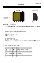
12. Overview of electronic indicators
LED 1 indicator
LED 2 indicator
LED indicator
Control box
Remote control
After connecting the system to power:
1.
When a command is given with a remote control or hardwired, the LED
’
s will indicate the signal was recei-
ved.
-
LED 2 on the control box will flash orange, as the signal is received from a FOB or external devices like swit-
ches
-
LED 1 will start to flash green, as power is converted to 32 VDC
-
For the meaning of all other LED indications, see the chart below.
2.
The following conditions must be met:
-
Sufficient input voltage
-
Sufficient output voltage
-
No obstruction in door path.
-
No block signal active (ignition lockout)
-
All FOB components are programmed to the receiver in the box. Upon initial power up, the first allowed
function is the door
‘
UP
’
function.
How does the control box work? LED explanation
LED
Colour
Sequence
Issue/Function
LED 1
Red
Flash
Low voltage input (during operation)
LED 1
Green
Solid
Power in
LED 1
Green
Flash
In operation
LED 2
Orange
Flash
Signal received
LED 2
Orange
Solid
Warning, overload motor
-
unit / obstruction
LED 2
Red
Solid
Error, time out door travel
Installation guide

