background image

21


DoorLIFT DL

-

6


Remote door system


8.6 Connecting to the battery


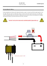
On the pig

-

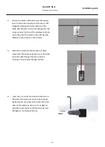
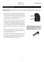
tailed end of the DoorLIFT battery cable, splice red wires , and one end of the fuse wire together. A sol-

der splice with heat shrink is recommended. Crimp a terminal to the other end of the fuse wire. This will be atta-
ched to the positive battery terminal. Splice the black wires with a terminal which will be attached to the negative 
terminal of the battery. Connect the connector end to the control box. 


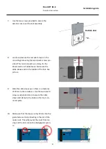
Push in until you hear it 

click


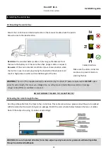
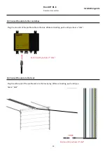
DO NOT PUT IN THE FUSE UNTIL FURTHER NOTICE (CHAPTER 12)


X


30A fuse


Installation guide


Summary of Contents for DoorLIFT DL-6

Page 1: ...INSTALLATION GUIDE Version 10 2020 Need help For assistance with this product please visit www actuall eu ...

Page 2: ...2 ...

Page 3: ...g rod 11 6 2 Checking the turnbuckle connecting rod 13 7 Installing the emergency release cable system 14 7 1 Drilling the holes 14 7 2 Installing the lock 14 7 3 Installing the release cable 15 8 Installing the control box 18 8 1 Mounting the control box 18 8 2 Feeding the cable through the box 18 8 3 Connect the cable to the control box 19 8 4 Connect the cable to the track 19 8 5 Optional funct...

Page 4: ... hinges or rollers etc 5 Is the top panel of the door strong enough or will it require reinforcement to prevent it from flexing during the closing cycle 6 Is the power supply adequate The system requires a 12 or 24 volt 65 amp source Has the battery and charging system been well maintained Batteries that are poorly maintained or highly discharged may not be able to operate the system The Low volta...

Page 5: ... If there isn t enough clearance contact your shutter door supplier to enquire whether the track can be modified to allow installation of the DoorLIFT 2 3 Checking the top roller brackets Make sure that the right type of top closure arm is installed on your door to be sure that the door closes in the right way You will need an adjustable type with two rollers to give the best result This also will...

Page 6: ...rom the track This only can be done by removing the rear cover and slide the 700 mm long motor unit out of the track Note If the length of the aluminium track needs to be reduced the cut must be made at rear of the track furthest from the door opening The shortest length of track required to operate properly is door height 92 cm 4 Shutter door reinforcement is needed in case of a plastic type door...

Page 7: ...s only recommended if there is an alternative entry into the cargo area side door or cab pass through If the door does not open for any reason you will have no access to the control box without these alternative entry points Insulated trucks or trailers will require some additional support in the ceiling before installing the DoorLIFT rail Do not attempt to install the DoorLIFT track to an unsuppo...

Page 8: ...d NOTE Depending on the roof body structure the installer is required to decide on the type of fasteners and amount of connections NOTE Keep a space of 20 30 mm between the front of the track and the balancer 20 30 mm Place the left side facing the door of the track allong the line Keep a clearance between balancer and track BE AWARE when the distance between track and balancer is too much it will...

Page 9: ...and the next makes lifting the track assembly easier Move the lever shown at the right to the manual position The motor unit can now be moved by hand Moving the lever towards the battery icon will put the motor unit back in automatic mode Use large diameter head screws or rivets where the screw heads or rivet heads do not protrude more than 1 8mm from their seated position The motor unit will hit ...

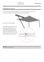
Page 10: ...motor as close to the door as possible raise the door slightly to ensure the tab on the connector plate is aligned with the tab on the motor unit Once you are satisfied with the position of the connector plate secure it to the top panel Dry freight door connection plate Insulated freight door connection plate or Place the door connection plate in te center of the door Center line Center line 9x IM...

Page 11: ...oor as far as it will go then slide it back from the stop screw approximately 50mm See marker on the track Lock the motor at this position NOTE This is very important The motor unit should never touch the screw Measure A Dry freight Meassure A Insulated freight Select the right holes and measure the distance in between 6 1 Installing the turnbuckle connecting rod Installation guide ...

Page 12: ... the system will be interfered when the rod does protrude into the fork The length of the threaded rod is Measurement A 70 mm Cut the threaded rod to length Install the connection bar in the previous selected holes and secure the nut 13 mm Installation guide ...

Page 13: ...degrees 25mm After installation the connection bar should be in a 30 45 degree angle when the door is in closed position The motor unit should always be 25mm away from the end screw 6 2 Checking the turnbuckle connecting rod Installation guide ...

Page 14: ... completely through as per drill template 7 2 Installing the lock 1 Locate the lock assembly turn the key 90 degrees and remove the core of the lock from the lock housing plate Insert the housing plate into the holes on the face of the door Use masking tape if necessary to hold the housing to the face of the door 2 Select the appropriate length screw from the kit and secure the interior mounting p...

Page 15: ...ge the lever lock the DoorLIFT With the lever engaged push the cable 50mm further into the motor You can temporarily hold the cable 50mm past the lever with masking tape to keep it from moving 2 Slide the cable sleeve over the cable and 50mm into the guide tube in the motor housing 3 Mark the sleeve 25mm below the door connector plate Remove the sleeve and cut it on the mark DO NOT CUT THE CABLE S...

Page 16: ... become difficult to insert into the lock cylinder 5 Slide the red tube the 60mm piece of cable sleeve and the plastic cover base over the cable Push the cable through the door and lock housing so it protrudes through the face 6 Insert the cut end of the cable into the hole on the back of the lock core Secure the cable by tightening the set screw on the side of the core with a 2mm Allen key Be sur...

Page 17: ...ure the cable sleeve ends in the middle of the lock See picture 9 Slide the cable sleeve up so there is a clearance of 30mm to the red sleeve Use the two 4 8x19 screws and plastic clamp to secure the cable sleeve and clamp to the holes on the door con nector plate 10 Make sure that the sleeve is only 50mm into the guide tube and not protruding in the slot of the motor unit This will prevent the le...

Page 18: ...e down to prevent moisture entering the box WARNING The size of the supplied cable s is determined by the DoorLIFT power requirements DO NOT splice wires for extra length this can cause voltage drop resulting in poor intermittent operation or damage Longer cable till 5m is available on request DO NOT CONNECT THE BOX TO THE BATTERY YET 8 2 Feeding the cable through the box Run the profile cable fro...

Page 19: ...nd of the profile cable to the track plug While connecting push until you hear a click DoorLIFT DL 6 Remote door system Push in until you hear it click Plug the one end of the profile cable to the box While connecting push until you hear a click Push in until you hear it click Installation guide ...

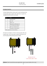
Page 20: ...ary devices to the DoorLIFT control box through the 8 lead auxiliary harness using the wire chart below as a guide The pig tailed end of the harness has numbers The 8 pin male receptacle on the box comes equipped with a plug to protect the connector from water and dirt if the harness is not used This plug is removed if the harness is utilized WARNING Protect unused harness leads against water debr...

Page 21: ...heat shrink is recommended Crimp a terminal to the other end of the fuse wire This will be atta ched to the positive battery terminal Splice the black wires with a terminal which will be attached to the negative terminal of the battery Connect the connector end to the control box Push in until you hear it click DO NOT PUT IN THE FUSE UNTIL FURTHER NOTICE CHAPTER 12 X 30A fuse Installation guide ...
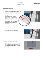
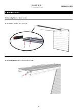
Page 22: ...22 DoorLIFT DL 6 Remote door system 9 Adjusting the sensors 9 1 Adjusting the door closed sensor Remove the rear cover from the track Remove the plastic cover on the side of the track Installation guide ...

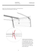
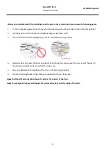
Page 23: ...cted motor unit manually Set the sensor switch A sideways to match the cable slider magnet B Both screw heads should be in line see pic ture The cable slider contains the mag net that moves with the motor unit and trips the sensor switches to signal the control box that the door is either fully opened or fully closed A B Installation guide ...

Page 24: ... desired height WARNING Do not adjust the DoorLIFT to open the door too far The lock on the face of the door can jam against the DoorLIFT track on the ceiling Using an Allen key slide the sensor switch A to the desired location The sensor switch adjustment bolt should be 10 mm ahead of the cable slider magnet B bolt relative to the cab end of the track Do not install the track wire trim or track e...

Page 25: ...to the system because the me mory has been erased The UNLOCK OUTPUT will trigger to tell you the transmitter has been recognized and is compatible with the system A maximum of 12 transmitters can be coded per sys tem 3 During code learning if there is no action after 5 seconds the system will exit learning mode The UNLOCK OUTPUT will sound indicating its leaving learning mode 4 If old FOBs have to...

Page 26: ...door The door should close tightly against the floor If the door closes and then raises approximately 15cm the closed switch needs to be ad justed Loosen sensor switch on the side of the track and slide the sensor switch towards the front of the truck Test the close function again repeat the process as necessary page 22 6 Once you are satisfied with door s open and close positions install the sens...

Page 27: ...ceptable angle 30 45 with the door fully closed 4 When the door is closed the motor should not be touching the stop screw at the door end of the track it should approximately be 25mm behind the stop screw 5 Are you satisfied with the position of the door in the fully open position 6 Is there still enough slack in the emergency cable with the door fully open Apply the DoorLIFT warning label above t...

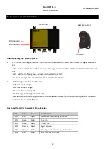
Page 28: ...g of all other LED indications see the chart below 2 The following conditions must be met Sufficient input voltage Sufficient output voltage No obstruction in door path No block signal active ignition lockout All FOB components are programmed to the receiver in the box Upon initial power up the first allowed function is the door UP function How does the control box work LED explanation LED Colour ...

Page 29: ...29 DoorLIFT DL 6 Remote door system Installation guide ...

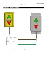
Page 30: ...stem 13 Appendix A Push buttons DL 8000810 Colour Wire Function Brown 2 Up White 3 Down Green 5 12V Use the 8 wire auxiliary cable to connect the push buttons to using the numbered wires as shown in the table above Installation guide ...
Page 31: ...31 DoorLIFT DL 6 Remote door system Installation guide ...

Page 32: ...Actuall Innomotive International BV Energieweg 52 3771NA Barneveld The Netherlands 31 0 33 7074 889 www actuall eu ...

Reviews: