11
20210408 - LNNN00354 (3.0) Swegon reserves the right to alter specifications.
Actionair DWFX-F Installation Guide
Actuators
Control Mode Installation Procedure
1.
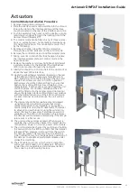
Remove transit plate and recycle.
2. Slide the interface and mode assembly into the shroud.
Ensure the slots in the interface casing and the drive
coupling located on the rear of the interface are in line.
3. Push the assembly fully home until the interface sprung
retaining pin engages through the locating hole in the
damper shroud (snaplock™).
4.
The control mode can be fitted in any of three orienta
-
tions i.e. vertically down, horizontally and vertically up
(For height restrictions). This can easily be carried out
by the following:
5.
Remove and retain screw (8mm A/F) and washer,
through the position indicator on the control mode.
6.
Remove the control mode and interface adapter plate.
7. Taking care not to disturb the drive hexagon. Replace
the interface adapter plate and control mode in the
new orientation.
8.
Replace the washer and screw tight (Max 5Nm) Select
a suitable position for the Electrical Thermal Release
(ETR) to be mounted through the ductwork.
9. Ideally this should be in the top half of the duct and/ or
above the level of the interface.
10. Apply the self-adhesive template (located on the rear
of the ETR) and drill the necessary holes (Ø3mm &
Ø9.5 & Ø11mm). Push the ETR through the duct and
ensure both screws are used to hold it in position.
Both screws should be tightened fully to ensure that
both sections of the ETR are closed together. It is a
safety feature, if both sections are not closed the unit
will not operate. For ductless installations the ETR
should be fitted onto the damper spigot (not casing)
above the damper interface shroud and in accordance
with the fitting instructions. If the ETR is not fitted in
the exact manner described above, the unit will not
operate.
11. The damper should be manually reset and released
using the winder provided to ensure that correct
mechanical operation is achievable. It is possible to
mechanically lock open the SmokeShield PTC damper
to allow air to pass through it using the winder pro-
vided, this may be necessary if electrical power isn’t
available yet. The ETR is not operable in this instance,
the damper will not release automatically if the tempe-
rature rises or a fire occurs.
12. The unit must be wired as detailed. When power is
available, the unit must be checked for correct electri-
cal operation. Power on to reset, power off to release.
13. The unit must also be checked by pushing and holding
the test switch on the ETR to confirm that the damper
releases. When pressure is removed from the switch
the damper resets. This may also be done after the
initial installation test, to provide periodic operation of
the damper to simulate actual fail-safe release under
smoke/fire conditions.
14.
The ETR cable must not cut to shorten or lengthen,
and care must be taken not to damage it. Either will
render the unit inoperable and void any warranties.
This is due to a built in safety feature.


