Model SP33X-0700
4-Wire DC I/V Signal Splitter w/USB
Acromag, Inc. Tel: 248-295-0880
- 8 -
https://www.acromag.com
Page 1: ...Voltage Input Model SP337 0700 DC 1V 10V Medium Voltage Input Model SP338 0700 DC 15V 150V High Voltage Input USER S MANUAL ACROMAG INCORPORATED Tel 248 295 0880 30765 South Wixom Road Fax 248 624 923...
Page 2: ...onal Bus Power Connections 11 Earth Ground Connections 12 USB Connections 13 CONFIGURATION SOFTWARE 14 Quick Overview Android 14 Quick Overview Windows 15 OPERATION STEP BY STEP 18 Connections 18 Conf...
Page 3: ...f this manual may change without notice Acromag makes no warranty of any kind regarding this material including but not limited to the implied warranties of merchantability and fitness for its intende...
Page 4: ...bit conversion Adjustable scalable input output ranges SP336 has DC Current Input for 0 20mA 4 20mA 0 11 17mA 1mA and DC Voltage Input for 0 5V 0 500mV SP337 has separate DC Voltage inputs for up to...
Page 5: ...to tilt the unit upward to lift it from the rail while prying the spring clip back with a screwdriver To attach the module to T type DIN rail angle the top of the unit towards the rail and place the...
Page 6: ...nals are pluggable and can be removed from their sockets by prying outward from the top with a flat head screwdriver blade This model allows current input to be wired to TB1 and voltage input wired to...
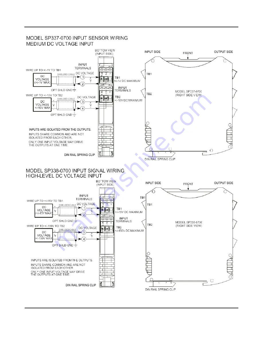
Page 7: ...utputs at one time An output may drive current or voltage on separate terminals that share RTN The input may be scaled differently for each output Input is polarized observe proper polarity The positi...
Page 8: ...Model SP33X 0700 4 Wire DC I V Signal Splitter w USB Acromag Inc Tel 248 295 0880 8 https www acromag com...
Page 9: ...ng is often used to connect the longest distance between each field transmitter output and the remote load as shown above Additionally shielded twisted pair wiring is recommended for best results An o...
Page 10: ...ly without wiring power to each power terminal block individually Power connections are isolated from the input and each output The supply voltage should be from 6 32V DC This voltage must never excee...
Page 11: ...ector is diode coupled to the same point in the circuit as unit power connected at power terminal TB5 You could power multiple units by snapping them together along the DIN rail bus using connector 10...
Page 12: ...tion is typically required for the enclosure and you should connect that metal enclosure s ground terminal green screw to earth ground using suitable wire per applicable codes See the Electrical Conne...
Page 13: ...tion is recommended and required when connected to a grounded input Input and USB connections are isolated from each output and power of this model USB Isolation is recommended for safety and noise su...
Page 14: ...wipe left or right to view more diagrams No connection is required to view the diagrams Android requires user permission to access external hardware If the Device List displays No Device Permission se...
Page 15: ...ws Communication Set up I O Config Test and Calibration A short description of each of these configuration pages follows Communication Set up First Connect to Unit Here Select from connected transmitt...
Page 16: ...anual Test I O Optional Verify Unit Operation Here After making I O configuration changes you can use the TEST I O controls to start stop polling the input channel to check your input readings Click t...
Page 17: ...t Cal Instructions button to begin output calibration You will be prompted to adjust the input signal as required to drive the output to its precise output range zero or full scale level Then once the...
Page 18: ...for either current or voltage as required by your application You will need to measure output current or voltage accurately to calibrate the output You could connect a current meter in series with the...
Page 19: ...e unit via USB and the unit s model serial information will appear in the Device field as shown in the second screen at left If you happen to be connected to more than one unit via a USB hub you can u...
Page 20: ...aking changes Otherwise if you have loaded the configuration from a saved file or have made changes to any fields you can click the Get I O Config button at the top of the screen to retrieve the conne...
Page 21: ...I O Scaling You may rescale a selected input range differently for each output channel and you could choose to use a smaller portion of the nominal input range to drive an output if desired Likewise y...
Page 22: ...ter as desired before calibrating the input Calibration of this model is a simple two part process initiated by simply clicking the Input Cal or Output Cal Instructions button to begin and then follow...
Page 23: ...l scale signal level If your output acts erratic or appears imprecise you may need to repeat input or output calibration being very careful to take accurate measurements and input correct signal level...
Page 24: ...red to optional bus power terminals along the DIN rail Set up involves selecting the input range current or voltage selecting the output range at each output current or voltage selecting a filter leve...
Page 25: ...short this bias to earth ground and clip the negative input range with a non isolated USB connection For this reason and for increased safety and noise immunity it is best to connect to USB via a USB...
Page 26: ...of your input sensor If you are not isolating USB check for a ground loop between a grounded sensor and earth ground of the PC USB port Cannot Calibrate Input Channel Is input wired properly Check th...
Page 27: ...olator USB Isolator Order USB ISOLATOR USB Signal Isolator USB A B Cable 4001 112 Instructions 8500 900 This kit contains a USB isolator and a 1M USB A B cable for connection to a PC This isolator and...
Page 28: ...k male connector 1005 221 Two End Stops for 35 mm DIN Rails 1027 222 not shown Series SP splitters are shipped with their bus port plugged Remove this plug and insert DIN Rail Bus Connector 1005 063 s...
Page 29: ...hese models have two separate inputs for current and or voltage depending on the model but only one input may drive the output at a time On SP336 DC current is input at TB1 and DC voltage at TB2 On SP...
Page 30: ...typical SP336 14V working and 18V clamp level typical and 14V working SP337 and 220V working voltage typical SP338 All inputs to ADC also include differential input diode clamping capacitive filterin...
Page 31: ...DC TB2 NONE 2 6554 to 58982 or 1 52428 0 to 500mV DC TB2 NONE 2 32768 to 58982 or 1 26214 SPx37 INPUT RANGE xDIVIDER xGAIN A D INPUT RESOLUTION1 1V to 1V DC TB1 NONE 1 6554 to 58982 or 1 52428 0 to 1...
Page 32: ...Sensor Turns Range for SP336 Model Only AC Current Input Range Primary Turns Sensor Output Red Black 0 to 20A AC 1 0 to 11 17mA DC 0 to 10A AC 2 0 to 5A AC 4 0 to 2A AC 10 0 to 1A AC 20 AC Input Burde...
Page 33: ...with nominal input and output ranges This includes the effects of repeatability terminal point conformity and linearization but does not include sensor error Output Noise Ripple Less than 0 1 of outpu...
Page 34: ...not used by the module 2 Differential Data 3 Differential Data 4 NC Not Connected 51 Power Ground Connects directly to Signal Ground SHLD1 Signal Ground Connects directly to Signal Ground 1 Note Most...
Page 35: ...ectors Removable plug in type terminal blocks rated for 12A 250V AWG 26 12 stranded or solid copper wire Program Connector 5 pin Mini USB B type socket Hirose UX60 MB 5S8 DIN Rail Mounting Unit is nor...
Page 36: ...ty EMC CE Marked per EMC Directive 2014 30 EU FCC Conformity This device complies with Part 15 Class B of the FCC rules Safety Approvals UL Listed USA Canada Hazardous Locations Class I Division 2 Gro...
Page 37: ...rs are used to adjust this transmitter Its behavior as an isolated signal amplifier transducer is determined via programmed variables set using a temporary USB connection to a host computer or laptop...