SERIES AP220 / AP231 ACROPACK
USER
’S MANUAL
Acromag, Inc. Tel: 248-295-0310
- 29 -
http://www.acromag.com
- 29 -
https://www.acromag.com
Equation (1):
𝑰𝒅𝒆𝒂𝒍𝑪𝒐𝒅𝒆 = [𝑰𝒅𝒆𝒂𝒍𝑺𝒍𝒐𝒑𝒆 × 𝑫𝒆𝒔𝒊𝒓𝒆𝒅𝑽𝒐𝒍𝒕𝒂𝒈𝒆] + 𝑰𝒅𝒆𝒂𝒍𝒁𝒆𝒓𝒐𝑪𝒐𝒅𝒆
where,
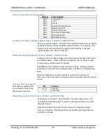
Table 3.11 AP231
Model
Ideal slope and zero values
for supported ranges.
Range
IdealSlope
IdealZeroCode
Straight Binary(2’s Comp)
-10 to 10V
3276.8
32768 (0)
-5 to 5V
6553.6
32768 (0)
-3 to 3V
10922.67
32768 (0)
-2.5 to 7.5V
6553.6
16384 (-16384)
0 to 10V
6553.6
0 (-32768)
0 to 5V
13107.2
0 (-32768)
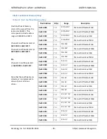
Table 3.12 AP220 Model
Ideal slope and zero values
for supported ranges.
Range
IdealSlope
IdealZeroCode
Straight Binary(2’s Comp)
-10 to 10V
204.8
2048 (0)
-5 to 5V
409.6
2048 (0)
-3 to 3V
682.6
2048 (0)
-2.5 to 7.5V
409.6
1024 (-1024)
0 to 10V
409.6
0 (-2048)
0 to 5V
819.2
0 (-2048)
Using equation (1), one can determine the
IdealCode
for any desired voltage
within the range. For example, if it is desired to output a voltage of +5 Volts
for -10 to 10V range, equation (1) returns the result 49,152 for
IdealCode
for
Model AP231. If this value is used to program the DAC output (following
conversion to Hex 0xC000), the output value will ap5 Volts to within
the uncalibrated error. This will be acceptable for some applications.
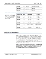
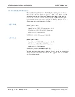
For applications needing better accuracy, the software calibration
coefficients should be used to correct the
IdealCode
into the CorrectedCode
required to accurately produce the output voltage. This is illustrated in
equation (2):

