SERIES AP220 / AP231 ACROPACK
USER
’S MANUAL
Acromag, Inc. Tel: 248-295-0310
- 13 -
http://www.acromag.com
- 13 -
https://www.acromag.com
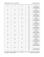
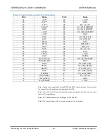
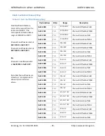
52
43
36
69
72
Reserved/isolation
71
Reserved/isolation
19
19
37
74
53
44
38
73
76
Reserved/isolation
75
Reserved/isolation
20
20
39
78
54
45
40
77
80
Reserved/isolation
79
Reserved/isolation
21
21
41
82
55
46
42
81
84
Reserved/isolation
83
Reserved/isolation
22
22
43
86
56
47
44
85
88
Reserved/isolation
87
Reserved/isolation
23
23
45
90
57
48
46
89
92
Reserved/isolation
91
Reserved/isolation
24
24
47
94
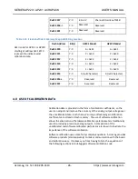
EXT_VSS_DAC
58
49
48
93
Signal Return
96
Reserved/isolation
95
Reserved/isolation
25
25
49
98
EXT_VDD_DAC
59
50
50
97
Signal Return
100
Reserved/isolation
99
Reserved/isolation
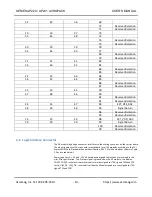
2.8 Logic Interface Connector
The AP module logic edge connector interfaces to the mating connector on the carrier board.
The pin assignments of this connector are standard for all AP modules according to the PCI
Express MINI Card Electromechanical Specification, REV 1.2 (with exceptions shown in Table
2.2 and noted below).
Power su5, +12, and -12 Volt have been assigned to pins that are reserved in the
mini-PCIe specification. The Present signal is grounded on the AP module. In addition,
COEX1, COEX2
–
wireless transmitter control are reassigned to JTAG signals TMS and TCK
Lastly, UIM_C4, UIM_C8
–
reserved User Identity Module signals are reassigned to JTAG
signals TDI and TDO.


