Page 29 of 33
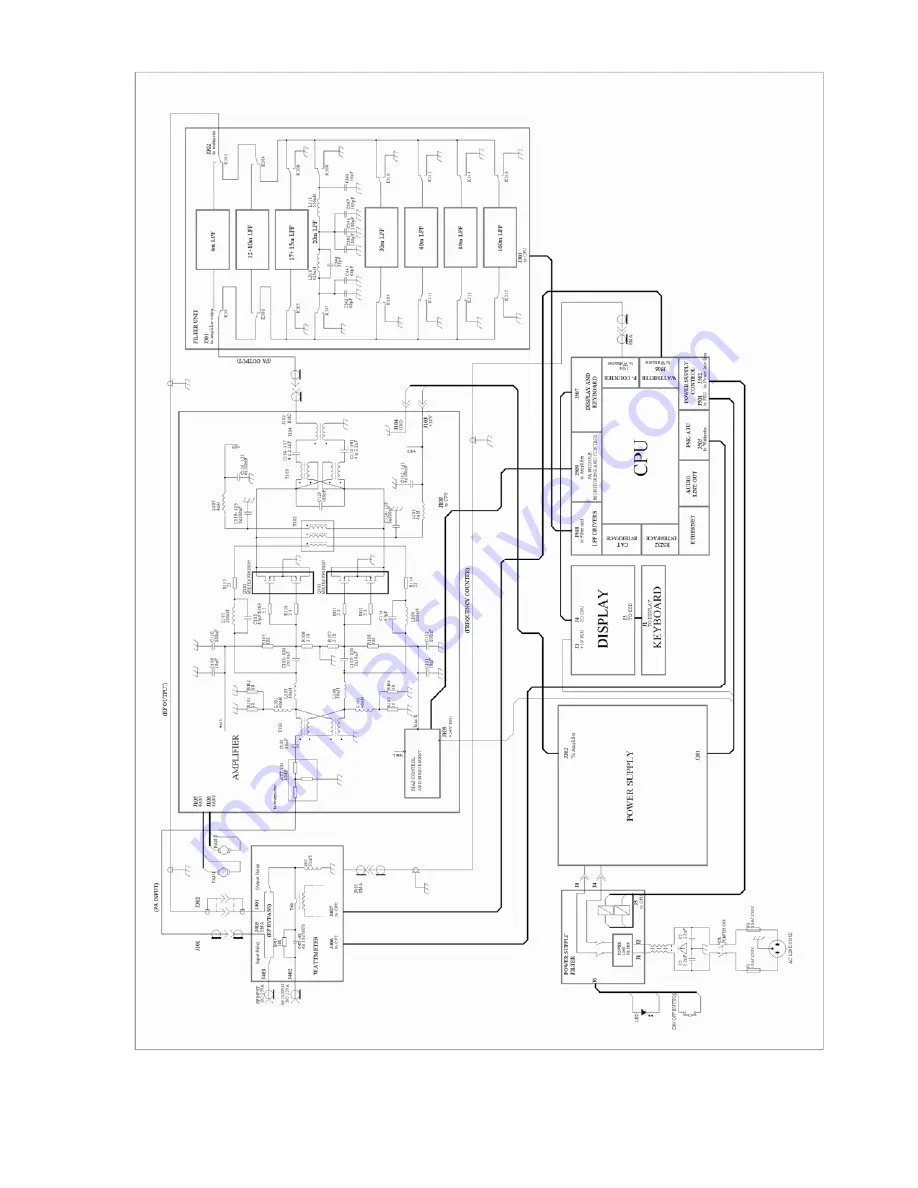
Fig. 7-1 ACOM 600S Simplified Schematic Diagram
Page 1: ...HF 6 m LINEAR AMPLIFIER OPERATING MANUAL ...
Page 2: ...e Stand by option AUTO OPERATE 16 4 2 Band change standard and expanded frequency coverage 17 4 3 Change of antennas and operation with an external antenna tuner 18 4 4 Cooling and fans operation modes with increased heat loading 18 4 5 Monitoring the amplifier operating regime 18 4 6 Automatic protection system 18 5 MENUS USEFUL INSTRUMENTS AND OPTIONS 20 5 1 Menu Measurements in the amplifier AM...
Page 3: ... the supported transceiver models please specify the wanted one Technical compact disk CD containing complete schematic diagrams graphic information and parts layouts of the printed circuit boards as well as a list of commands set and the rules for remote control of the ACOM 600S amplifier 1 4 Features 5 108x65mm high resolution color display 800x480 pixels and 24 bits colors The final stage uses ...
Page 4: ...of the shack for safe operation The ACOM 600S amplifier is designed to meet international safety standards and complies with CE safety and electromagnetic compatibility requirements as well as FCC regulations This operating manual contains an assortment of precautions indications for cautions and warnings that MUST BE FOLLOWED by the user to ensure safe operation and always maintain the ACOM 600S ...
Page 5: ...warranty conditions of the carrier N O T E Keep the original packing for possible future transportation Take out and inspect carefully the contents of the cardboard carton for possible transportation damages On the amplifier check the chassis the front panel the display and the buttons below it and on the rear panel all connectors the main power switch the fuses and the integrity of the power cabl...
Page 6: ...y all check ups described above first connect the grounding stud of the amplifier located on the rear panel and marked GND Fig 2 1 to the grounding system of the shack b KEY IN jack amplifier input for receive transmit control from the transceiver The transceiver switches the amplifier from receive mode into transmit mode RX TX via grounding of the KEY IN input Connect a shielded cable from the re...
Page 7: ...d that its closed circuit current is below 20mA If your transceiver has a suitable input which disables transmission unless it is grounded externally we recommend that you connect it to the KEY OUT jack of the amplifier Use shielded cable terminated with а standard RCA PHONO jack plug The manufacturers of transceivers give different names to this transceiver input for example TX INHIBIT MUTE LINEA...
Page 8: ...our nominal mains voltage C A U T I O N If your amplifier has only one mounted mains fuse Fig 2 1 S 7 2 it is suitable ONLY for power mains networks of the type 0 220 240VAC which are standard in the EU C A U T I O N Make sure you check whether the main fuses installed in your amplifier correspond to your mains nominal voltage and if necessary replace them as described in Section 7 2 Because of di...
Page 9: ... TTL input 11 ON RMT Remote Pwr On 4 5 to 15V 3mAmax 1 to 2 seconds pulse 12 Debug mode CPU only Power Input 8 to 15V 0 4A 13 KEY IN Transmit Request Rx Tx control input Less than 12 6V Less than 6mA 14 KEY OUT Transmit Enable O C output 0 to 50V 20mA maximum 15 GND Ground 0 Volt N O T E Due to the variety of existing CAT protocols for different transceivers the amplifier response may be different...
Page 10: ... 2 INSTALLATION and have followed all requirements check whether mains switch on the rear panel is in turned off position in Fig 2 1 the rocker of the POWER ON switch must be protruding from the side of the ON inscription Afterwards insert the mains plug of the amplifier into the mains outlet prepared for it For now the amplifier remains turned off 3 1 Low energy waiting mode of the power supply N...
Page 11: ...n power supply at starting amplifier operation press and hold on the ON OFF button on the front panel for one or two seconds аbout three seconds later the display will flash and show the basic screen showing the amplifier status and operation Fig 3 2 After turning on the amplifier stands in Stand by or Operate mode it depends on whether the AUTO OPERATE option has been activated see S 5 4 USER PRE...
Page 12: ...n the measurements indication is restored too c Indicator for the working mode OPR STB or AUTO OPER S 4 1 d Indicator RX TX reflects the state of the request for transmit KEY IN input The RX indication is green and the TX is red When a request is present but it could not be performed for any reason the respective indicator RX or TX is flashing frequently e Bar graph and digital indicator for forwa...
Page 13: ...stest return to the basic screen Fig 3 2 For more details on the control system and use of the menus see Section 5 MENUS USEFUL INSTRUMENTS AND OPTIONS 3 6 Test transmission To make sure that you have installed the amplifier correctly before you put it in operation make a test transmission as described below Repeat these tests for each new band and antenna as well as after installing a new or repa...
Page 14: ...his state repeat the receive and transmit tests with the transceiver through the amplifier RF by pass path as it was described in the preceding item a During these tests note also whether the bar graphs and digital indicators for forward and reflected power in the basic screen S 3 4 e f show respective RF power presence If the reflected power exceeds the forward power verify that you have not inte...
Page 15: ...nd down of the amplifier to switch to the desired frequency band manually In order to continue with the test transmission prepare the transceiver regime in the same way as it was done in item a above with continuous carrier mode and minimum power Now in the Operate RX mode choose a frequency which is presently not occupied and press the actuator for transmit PTT briefly while watching the followin...
Page 16: ...he antenna itself as well as at the feeder entering the building although this may seem unnecessary at GP take away as far as possible also by height the radiating elements of the antennas from the premises where the affected apparatus is located in this sense asymmetrical antennas without a feeder type Long Wire simple Windom and other similar may cause more interference because their radiating e...
Page 17: ...does not influence over its operation and the KEY OUT output S 2 3 c follows the state of the KEY IN input unconditionally b In Operate mode the final stage of the amplifier is powered and it is fully functioning the receive transmit RX TX direction is controlled by the KEY IN input at open KEY IN Operate RX mode the transceiver receives the signals from the antenna through the same RF by pass pat...
Page 18: ...rface or to a computer with the RS232 interface the change of the frequency bands i e change of the amplifier harmonic filters occurs automatically following the operating frequency changes from the transceiver or from the computer N O T E In the Stand by mode the change of bands through the CAT AUX interface is deactivated temporarily It is restored at returning to the Operate mode The RS232 band...
Page 19: ...perature humidity atmospheric pressure etc 4 5 Monitoring the amplifier operating regime Because of the availability of a continuously operating protection system in the amplifier S 4 6 the operator is not required to monitor its regime regularly However whenever he wishes he can digitally measure the 11 most important parameters connected with the amplifier operating regime Besides this the opera...
Page 20: ... by mode for four seconds or permanently depending on whether the AUTO OPERATE option had been activated Return into Stand by mode is accompanied with the respective message on the screen for example Excessive Reflected Power Excessive Drain Current and others as well as with a sound signal unless its volume had not been decreased to zero S 5 4 Unlike those for a WARNING the SOFT FAULT messages re...
Page 21: ...others Your dealer or his service may ask you to read through this data by RS232 interface or from the amplifier screen and store it in a computer file see menu FAULTS LOG Sections 5 5 and 7 4 5 MENUS USEFUL INSTRUMENTS AND OPTIONS From the basic screen Fig 3 2 pressing of the same name MENU button the rightmost the list with the six menus appears Fig 5 Each of them can be selected by means of but...
Page 22: ...2 b Fig 3 2 after leaving this menu EXIT button 5 2 Menu Service functions in the amplifier AMP SERVICE The amplifier service menu Fig 5 2 is accessible from the MENU SELECTION screen Fig 5 only during reception RX mode C A U T I O N The AMP SERVICE menu is used for check and adjustment of the zero signal idling drain current of the final transistors and for tests of some functions and circuits in...
Page 23: ...NGS is accessible only during reception Fig 5 and 5 3 After entering the menu with the ITEM buttons up and down the operator can mark the group of parameters which he will set top to bottom as listed on the screen The selected group is marked with color Afterwards with the SELECT buttons left or right the desired parameter is set it is enclosed within square brackets First choose the type of inter...
Page 24: ...enu by pressing the EXIT button the parameters enclosed currently within square brackets remain selected become effective 5 4 Menu USER PREFERENCES Here the operator can adjust some secondary minor functions of the amplifier according to his personal preferences Fig 5 4 Menu USER PREFERENCES ...
Page 25: ...wards again with the ITEM button the symbol for this position is changed they appear one after another in the order of the ASCII code Then with SELECT right the next symbol for editing is selected etc Finally again with SELECT left the small pointer returns backwards until it comes out of the cells for editing and only then with ITEM can be selected another row user preference When the EXIT button...
Page 26: ...he display a warning text appears about the action that would be implemented after confirming it At this stage the operator still has the opportunity to quit the execution of the prepared action he can press either the ACTION right NO or the EXIT button The time for confirmation of the prepared action by selecting YES is limited to 60 seconds in this state regardless of the current status of the A...
Page 27: ...rgy waiting mode using a serial command OFF change of the Operate Stand by mode this and next serial commands are accessible only when the main power supply is running change of the receive transmit RX TX mode change of the operating frequency BAND upgrade of the firmware change activation and deactivation of some options such as AUTO OPERATE OPERATE ACCESS the temperature scale unit ºC ºF reading...
Page 28: ... screwdriver to remove the square filter cover from the rear panel center see the four screws in Fig 2 1 Remove the cover and take out gently the foam like plastic filter Clean up the filter and the cover carefully from dust wash them with tap water and leave them to dry up before you mount them back While the air filter is drying clean the fan propeller and its body with a vacuum cleaner and a so...
Page 29: ...itude but 180º out of phase in anti phase The balanced choke transformer T102 in the power supply through its two main windings T102 and T102B feeds DC supply voltage 50V from Power Supply Unit connectors J103 and J104 to the drains of the transistors Q101 and Q102 the Power Supply Unit is described in c below The choke transformer T102 contains yet one third winding T102A which serves for creatio...
Page 30: ...Page 29 of 33 Fig 7 1 ACOM 600S Simplified Schematic Diagram ...
Page 31: ...onnection with computer or Remote Control Unit In order to facilitate the diagnostics of possible failure after which the amplifier modules should not be powered before the failure has been repaired a special regime is designed By means of a low power DC external source only the Control unit can be powered so that the data from its nonvolatile memory can be downloaded and saved in a computer plain...
Page 32: ...e fault codes signatures for diagnostics In the nonvolatile memory of the Control unit there is room for data of the last 28 protection trips of the type serious fault HARD FAULT see S 4 6 c These are the values of all logic and analogous signals concerned to the regime and control of the amplifier as well as the time when a problem has occurred in worked hours and others The information can be pr...
Page 33: ...50 MHz 18 068 18 168 MHz 21 000 21 450 MHz 24 890 24 990 MHz 28 000 29 700 MHz 50 000 54 000 MHz Extensions or changes of the frequency coverage are possible after negotiations with the manufacturer b Rated output power 600W 0 5dB PEP or continuous carrier without mode limitation c Intermodulation distortions IMD3 better than 28dB 30dB typically below the rated PEP output d Harmonic and parasitic ...
Page 34: ...AT AUX connector type DB 15 c Remote control through RS232 interface connector type DB 9 d Remote turn on through simultaneous activation of the signals DSR DTR and CTS RTS on the RS232 type DB 9 connector e Remote turn on turn off line ON_RMT input on the CAT AUX DB 15 connector DC voltage pulse 4 5 to 15V DC towards ground for 1 2s input current 3mA maximum 8 3 Storage and shipment a Environment...
Page 35: ...ACOM OOD Blvd Nikola Mushanov 151 1330 Sofia Bulgaria phone 359 2 920 96 55 fax 359 2 920 96 56 e mail acom acom bg com acom mail orbitel bg www acom bg com ...