background image

12 

3-

1 Mounting

3-

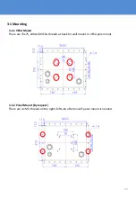
1-1 VESA Mount

There are 75x75, 100x100 VESA threads at back for wall mount or VESA pole mount.

3-1-2 Panel Mount (By request)

There are 4 x M4 threads on the right /left side of terminal if panel mount is needed.

Summary of Contents for PCM8011

Page 1: ...461F 810G Testing Compliance All rights reserved Product description and product specifications are subject to change without notice For latest product information please visit Acnodes website at www...

Page 2: ...2 CHAPTER 1 Declaration Please read this chapter with some important notice before operations...

Page 3: ...case the user will be required to correct the interference at him own expense Copyright Notice No part of this document may be reproduced copied translated or transmitted in any form or by any means...

Page 4: ...harges prepaid The returned product must be properly packaged in it s original packaging to obtain warranty service Customer Service The user guide includes simple debug and trouble shooting For syste...

Page 5: ...ve environment or such as on fire the overheat will cause the product malfunction You should avoid placing the product near explosive or firing environment If the product is close to the wet ground su...

Page 6: ...option is to use a damp cloth Do not touch the LCD panel surface with sharp or hard objects For pluggable equipment the power outlet must be installed near the equipment and must be easily accessible...

Page 7: ...ents places you would not take with normal commercial grade LCDs Panel PCs The mechanical is designed to be embedded in various kind of equipment This chapter tells you will find instructions for the...

Page 8: ...screen Default EMI Shield EMI Mesh filter applied Power DC 9 36V with power isolation surge protection Operating System Optional OS Windows 10 IoT Enterprise Linux Support Input Output D38999 connecto...

Page 9: ...9 2 2 I O Layout 1 2 3 No Connector No Description 1 D38999 24A98BN P1 DC Power Input 2 D38999 24WB35PN P2 2x USB 1x RS232 1x LAN 3 D38999 USBFTV71G P3 USB2 0 TypeA Receptacle...

Page 10: ...2 Signal Connector D38999 24WD35PN USB RS232 LAN Pin Pin Definition Interface 14 TX_D1 15 TX_D1 16 RX_D2 17 RX_D2 18 BI_D3 28 BI_D3 29 BI_D4 30 BI_D4 Pin Pin Definition Interface 27 CD 12 RXD 13 TXD...

Page 11: ...Operation When using a device be sure to read the instructions accompanying the device together with the relevant section in this chapter This chapter gives guidelines on using the device 11 CHAPTER 3...

Page 12: ...ng 3 1 1 VESA Mount There are 75x75 100x100 VESA threads at back for wall mount or VESA pole mount 3 1 2 Panel Mount By request There are 4 x M4 threads on the right left side of terminal if panel mou...

Page 13: ...heck chapter 4 in BIOS settings With pre installed OS system will automatically run with OS initialized procedure 3 2 Connection First of all please make the power cable according to the Pin table on...

Page 14: ...etup CHAPTER 4 BIOS Setup Utility is a program for configuration basic Input Output system settings of the HMI for optimum use This chapter provides information on how to use BIOS setup its functions...

Page 15: ...ain Run BIOS setup utility for 1 Error message on screen indicates to check BIOS setup 2 Restoring the factory default settings 3 Modifying the specific hardware specifications 4 Necessity to optimize...

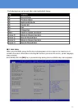
Page 16: ...to the previous item Cursor Goes to the next item Cursor Moves to the previous item Cursor Goes to the next item BIOS Main Menu When you enter BIOS setup the first menu that appears on the screen is...

Page 17: ...h mm ss Access Level The current user access settings Changes to the level of access Administrator is set up by the default Advanced Menu The advanced menu also uses to set configuration of the CPU an...

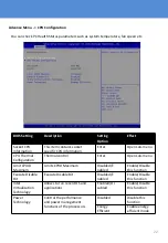
Page 18: ...n Configures PPM settings Enter Opens submenu Thermal Configuration Configures Thermal Parameters Enter Opens submenu IDE Configuration Configures IDE Parameters Enter Opens submenu Miscellaneous Conf...

Page 19: ...s You can use the screen to select options of ACPI configuration A description of the selected items will appear on the right side of the screen BIOS Setting Description Setting Option Effect Enable A...

Page 20: ...escription of the selected item appears on the right side of the screen For items marked with please press Enter for more options Serial Port 1 5 Use these items to set parameters related to serial po...

Page 21: ...can check PC Health Status parameters such as system temperature fan speed etc Advanced Menu S5 RTC Wake Settings Wake system from S5 enables or disables system wake on alarm event It allows you to w...

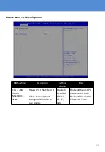
Page 22: ...control Enter Open sub menu Limit CPUID Maximum Limits CPIID Maximum Disabled E nabled Enable Disable this function Execute Disable Bit Execute Disable Bit Disabled E nabled Enable Disable this funct...

Page 23: ...Setting Option Effect CPU C State Report Shows CPU C State Report Enabled Disabled Enable or Disable CPU C state report to OS Max CPU C State Allows to enter power saving mode in order to save energy...

Page 24: ...ing Option Effect Critical Trip Point Specifies the temperature at which the OS will shut down the system 90C 87C 85C 79C 71C 63C 55C 47C 39C 31C 23C 15C Select the disable temperature for the system...

Page 25: ...Gen1 The maximum speed will be limited to 150 MB s Gen2 The maximum speed will be limited to 300 MB s Disabled Disables manual configuration of SATA II ports mode will be selected based on the specif...

Page 26: ...f Disabled Port 0 SATA Port0 HotPlug This feature that allows you to attach and remove a SATA Port0 Enabled Disabled Enable or disable this function Serial ATA Port 1 The option turns on or off Port 1...

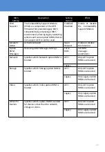
Page 27: ...ction Option ROM Messages Receiving ROM Messages Settings Force BIOS Set ROM messages parameters Network Specifies which Network option ROM is booted UEFI Only UEFI option ROMs are booted Legacy Stora...

Page 28: ...28 Advance Menu Platform Trust Technology BIOS Setting Description Setting Option Effect fTPM Trusted Platform Module parameters Enabled Disabled Enables or disables this function...

Page 29: ...sabled Enables or disables this function TXE Firmware Update TXE Firmware Update parameters Enabled D isabled Enables or disables this function TXE EOP Message TXE EOP Message parameters Enabled D isa...

Page 30: ...Disabled Enables Disable s this function Restore AC Power Loss This function allows to set up booting options after a power failure Power on Power off Boot automatically after a power failure Serial...

Page 31: ...password and HDD security configuration BIOS Setting Description Setting Option Effect Administrator Password Displays whether or not an administrator password has been set Enter Enter password User P...

Page 32: ...of the devices to be searched for the operating system The bootable devices will be automatically detected during POST and shown here allowing you to set the sequence that the BIOS uses to look for a...

Page 33: ...his function Fast Boot Enables or disables Fast Boot to shorten the OS boot process Default Disabled Disabled Disables this function Enabled Enables this function Boot Mode Select Specifies which mode...

Page 34: ...m Enter YES Save changes Discard Changes and Exit This exits the BIOS Setup without saving the changes made in BIOS Setup to the CMOS Enter YES Saves the changes Enter NO Return to the BIOS Setup Main...

Page 35: ...to the BIOS Setup Main Menu Restore Default Restore load default values for all the setup options Enter YES Saves the changes Enter NO Return to the BIOS Setup Main Menu Save as User Defaults Save th...

Page 36: ...g CHAPTER 5 This chapter covers the following topics Storage Notice Troubleshoot your LCD Monitor If your monitor fails to operate correctly consult the following chart for possible solution before ca...

Page 37: ...RS232 connection poor Please check the signal cable make sure each pin has correctly connected If Ethernet didn t run on Gigabit LAN speed please check all 10 pin has been well connected If USB power...

Reviews: