


Chapter 6
167
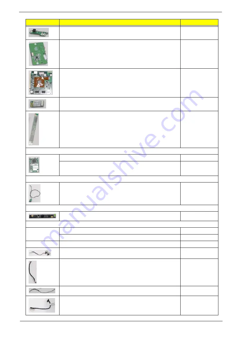
POWER BOARD
55.G8507.001
I/O BOARD W/CARD READER
55.G8507.002
VGA CARD M92XT_512M
VG.M9209.001
QMI QBT400UB Bluetooth Qcom Technology Inc., Broadcom
BCM2046, Bluetooth2.1 + EDR, USB interface module
BT.14500.001
INVERTER BOARD TWS-449-364
55.G8507.003
TV TURN
AverMedia A336-A Mini-Card WW ATSC Digital
TU.10500.051
AverMedia A336-D Mini-Card WW DVB-T Digital
TU.10500.052
IR Blaster
SMK IR BLASTER RWS9000-1301FP
RV.RWS07.001
WEBCAM
CAMERA 1.3M CNF706921004171L
57.G8507.001
POWER CORD
POWER CORD US-110V 3P
27.G8507.001
POWER CORD 1.8M BLACK EU 3P
27.SCY07.001
CABLE
USB PORT W/CABLE
50.G8507.001
CABLE - AUDIO/B TO MB
50.G8507.002
POWER CABLE
50.G8507.003
LVDS CABLE
50.G8507.004
CATEGORY
Acer Description
ACER PART NO.
Summary of Contents for ZX4800 Series
Page 6: ...VI Laptopblue ...
Page 10: ...X Table of Contents Laptopblue ...
Page 47: ...Chapter 2 37 Laptopblue ...
Page 53: ...43 Chapter 3 4 Lift the ODD bezel away 5 Close the ODD assembly Laptopblue ...
Page 57: ...47 Chapter 3 5 Forcefully pry the rear cover from the assembly i ii iii iv Laptopblue ...
Page 59: ...49 Chapter 3 4 Disconnect the audio cable from the audio board Laptopblue ...
Page 62: ...Chapter 3 52 7 Remove the HDD module from the bracket Laptopblue ...
Page 74: ...Chapter 3 64 15 Lift the mainboard shielding away from the chassis Laptopblue ...
Page 76: ...Chapter 3 66 4 Lift the WLAN module away Laptopblue ...
Page 82: ...Chapter 3 72 4 Remove the fan Laptopblue ...
Page 87: ...77 Chapter 3 4 Remove the cables from the guide clips Laptopblue ...
Page 97: ...87 Chapter 3 4 Lift the power board away from the bezel Laptopblue ...
Page 100: ...Chapter 3 90 4 Disconnect the webcam cable Laptopblue ...
Page 121: ...111 Chapter 3 13 Connect the LVDS cable 14 Adhere the LVDC cable protective cover Laptopblue ...
Page 138: ...Chapter 3 128 4 Connect the left and right touchscreen sensor cable connectors Laptopblue ...
Page 143: ...133 Chapter 3 4 Connect the two 2 LCD to inverter board cables 1 and 2 1 2 Laptopblue ...
Page 155: ...145 Chapter 3 4 Close the ODD Laptopblue ...
Page 193: ...183 Appendix B Laptopblue ...
Page 196: ...186 Laptopblue ...
Page 197: ...187 Laptopblue ...
Page 198: ...188 Laptopblue ...


