


1-22
Hardware Specifications and Configurations
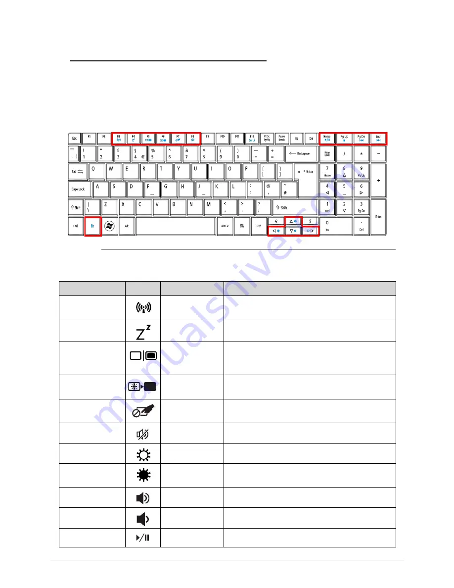
Hotkeys
0
The computer employs hotkeys or key combinations to access most of the computer's
controls like screen brightness and volume output.
To activate hotkeys, press and hold the
<Fn>
key before pressing the other key in the hotkey
combination.
Figure 1-8. Keyboard Hotkeys
Table 1-10. Hotkeys
Hotkey
Icon
Function
Description
<Fn> + <F3>
Communication
Enables / disables the computer's
communication devices.
<Fn> + <F4>
Sleep
Puts the computer in Sleep mode.
<Fn> + <F5>
Display toggle
Switches display output between the display
screen, external monitor (if connected) and
both.
<Fn> + <F6>
Screen blank
Turns the display screen backlight off to save
power. Press any key to return.
<Fn> + <F7>
Touchpad
toggle
Turns the internal touchpad on and off.
<Fn> + <F8>
Speaker toggle
Turns the speakers on and off.
<Fn> + <
>
Brightness up
Increases the screen brightness.
<Fn> + <
> Brightness
down
Decreases the screen brightness.
<Fn> + <
△
>
Volume up
Increases the sound volume.
<Fn> + <
▽
>
Volume down
Decreases the sound volume.
<Fn> +<Home>
Play/Pause
Play or pause a selected media file.
Summary of Contents for TravelMate P453-M
Page 1: ...Acer TravelMate P453 SERVICEGUIDE ...
Page 4: ...iv ...
Page 9: ...ix Introduction 8 3 ...
Page 10: ...x ...
Page 11: ...CHAPTER 1 Hardware Specifications ...
Page 14: ...1 4 ...
Page 57: ...CHAPTER 2 System Utilities ...
Page 67: ...System Utilities 2 11 Figure 2 9 Setup Warning ...
Page 85: ...System Utilities 2 29 Figure 2 37 GU bat ...
Page 88: ...2 32 System Utilities ...
Page 89: ...CHAPTER 3 Machine Maintenance ...
Page 92: ...3 4 ...
Page 99: ...3 11 3 Lift the bottom edge of battery bar first to remove the battery Figure 3 6 Battery ...
Page 101: ...3 13 3 Lift to remove the main door Figure 3 9 Main Door ...
Page 104: ...3 16 5 Remove the HDD bracket Figure 3 14 HDD Bracket ...
Page 107: ...3 19 Figure 3 19 ODD Bracket ...
Page 142: ...3 54 Figure 3 78 LCD Hinge CAUTION Distinguish the left and right hinge before assembling ...
Page 147: ...3 59 Figure 3 86 LCD Bezel ...
Page 158: ...3 70 3 Connect the cable from IO board to motherboard Figure 3 103 IO Board ...
Page 164: ...3 76 Figure 3 113 Top Case Module ...
Page 166: ...3 78 3 Lock 6 latches Esc F4 F8 F12 Del End around the keyboard Figure 3 116 Keyboard ...
Page 178: ...3 90 ...
Page 179: ...CHAPTER 4 Troubleshooting ...
Page 206: ...4 28 Troubleshooting ...
Page 207: ...CHAPTER 5 Jumper and Connector Locations ...
Page 215: ...CHAPTER 6 FRU List ...
Page 216: ...6 2 TravelMate P453 Exploded Diagrams 6 4 Main Assembly 6 4 FRU List 6 6 ...
Page 230: ...6 16 FRU Field Replaceable Unit List ...
Page 231: ...CHAPTER 7 Test Compatible Components ...
Page 232: ...8 2 Microsoft Windows 7 Environment Test 7 4 TravelMate P453 7 4 ...
Page 240: ...7 10 Test Compatible Components ...
Page 241: ...CHAPTER 8 Online Support Information ...
Page 242: ...9 2 Introduction 8 3 ...
Page 244: ...8 4 Online Support Information ...