


1-14
Hardware Specifications and Configurations
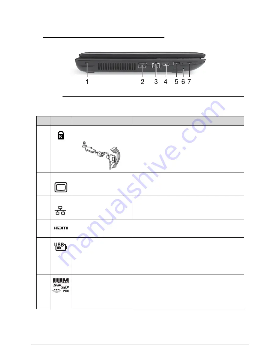
Left View
0
Figure 1-3. Left View
Table 1-3. Left View
No
Icon
Item
Description
1
Kensington lock slot
Connects to a Kensington-compatible computer
security lock.
Note:
Wrap the computer security lock cable
around an immovable object such as a table or
handle of a locked drawer. Insert the lock into the
notch and turn the key to secure the lock. Some
keyless models are also available.
2
External VGA port
Connects to a display device (e.g., external
monitor, LCD projector).
3
Ethernet (RJ-45) port
Connects to an Ethernet 10/100/1000-based
network.
4
HDMI port
Supports high-definition digital video connections.
5
USB 3.0 port with USB
charger
Connects to USB devices. Supports USB charge
Note:
A USB 3.0 port can be distinguished by its
blue connector.
6
ExpressCard/34 slot
Accepts one ExpressCard/34 module.
Note:
Push to remove/insert the module.
7
Multi-in-1 card reader
Accepts Secure Digital (SD), MultiMediaCard
(MMC), Memory Stick PRO (MS PRO), xD-Picture
Card (xD).
Note:
Push to remove/install the card. Only
one card can operate at any given time
.
Summary of Contents for TravelMate P453-M
Page 1: ...Acer TravelMate P453 SERVICEGUIDE ...
Page 4: ...iv ...
Page 9: ...ix Introduction 8 3 ...
Page 10: ...x ...
Page 11: ...CHAPTER 1 Hardware Specifications ...
Page 14: ...1 4 ...
Page 57: ...CHAPTER 2 System Utilities ...
Page 67: ...System Utilities 2 11 Figure 2 9 Setup Warning ...
Page 85: ...System Utilities 2 29 Figure 2 37 GU bat ...
Page 88: ...2 32 System Utilities ...
Page 89: ...CHAPTER 3 Machine Maintenance ...
Page 92: ...3 4 ...
Page 99: ...3 11 3 Lift the bottom edge of battery bar first to remove the battery Figure 3 6 Battery ...
Page 101: ...3 13 3 Lift to remove the main door Figure 3 9 Main Door ...
Page 104: ...3 16 5 Remove the HDD bracket Figure 3 14 HDD Bracket ...
Page 107: ...3 19 Figure 3 19 ODD Bracket ...
Page 142: ...3 54 Figure 3 78 LCD Hinge CAUTION Distinguish the left and right hinge before assembling ...
Page 147: ...3 59 Figure 3 86 LCD Bezel ...
Page 158: ...3 70 3 Connect the cable from IO board to motherboard Figure 3 103 IO Board ...
Page 164: ...3 76 Figure 3 113 Top Case Module ...
Page 166: ...3 78 3 Lock 6 latches Esc F4 F8 F12 Del End around the keyboard Figure 3 116 Keyboard ...
Page 178: ...3 90 ...
Page 179: ...CHAPTER 4 Troubleshooting ...
Page 206: ...4 28 Troubleshooting ...
Page 207: ...CHAPTER 5 Jumper and Connector Locations ...
Page 215: ...CHAPTER 6 FRU List ...
Page 216: ...6 2 TravelMate P453 Exploded Diagrams 6 4 Main Assembly 6 4 FRU List 6 6 ...
Page 230: ...6 16 FRU Field Replaceable Unit List ...
Page 231: ...CHAPTER 7 Test Compatible Components ...
Page 232: ...8 2 Microsoft Windows 7 Environment Test 7 4 TravelMate P453 7 4 ...
Page 240: ...7 10 Test Compatible Components ...
Page 241: ...CHAPTER 8 Online Support Information ...
Page 242: ...9 2 Introduction 8 3 ...
Page 244: ...8 4 Online Support Information ...