


Troubleshooting
4-5
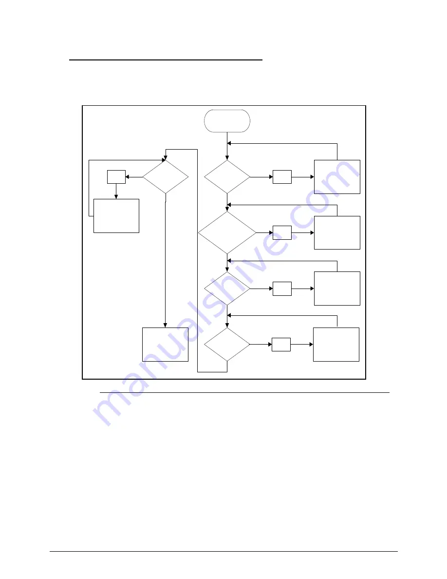
No Display Issues
0
If the Display does not work, perform the following, one at a time. Do not replace a
non-defective FRU:
Figure 4-2. No Display Issue
No POST or Video
0
If the POST or video does not appear, perform the following, one at a time.
1. Make sure that internal display is selected. Switching between internal and external by
pressing
Fn+F5
. Reference Product pages for specific model procedures.
2. Make sure the computer has power by checking for one of the following:
Fans start up
Status LEDs illuminate
If no power, refer to
Power On Issues
.
3. Drain stored power by removing the power cable and battery. Hold the power button for 10
seconds.
4. Connect the power and reboot the computer.
START
Power On?
Ext.DDRRAM
Module well
connected?
Ext DDRRAM
Module OK?
CPU Thermal
Module well
screwed?
LCD Moduel
OK?
NG
Power On Issue
Replace MB
NG
Check Connection
NG
Replace
Ext. DDRRAM
Module
NG
Fasten Screw
NG
Replace LCD
Panel/LCD Cable
Summary of Contents for TravelMate P453-M
Page 1: ...Acer TravelMate P453 SERVICEGUIDE ...
Page 4: ...iv ...
Page 9: ...ix Introduction 8 3 ...
Page 10: ...x ...
Page 11: ...CHAPTER 1 Hardware Specifications ...
Page 14: ...1 4 ...
Page 57: ...CHAPTER 2 System Utilities ...
Page 67: ...System Utilities 2 11 Figure 2 9 Setup Warning ...
Page 85: ...System Utilities 2 29 Figure 2 37 GU bat ...
Page 88: ...2 32 System Utilities ...
Page 89: ...CHAPTER 3 Machine Maintenance ...
Page 92: ...3 4 ...
Page 99: ...3 11 3 Lift the bottom edge of battery bar first to remove the battery Figure 3 6 Battery ...
Page 101: ...3 13 3 Lift to remove the main door Figure 3 9 Main Door ...
Page 104: ...3 16 5 Remove the HDD bracket Figure 3 14 HDD Bracket ...
Page 107: ...3 19 Figure 3 19 ODD Bracket ...
Page 142: ...3 54 Figure 3 78 LCD Hinge CAUTION Distinguish the left and right hinge before assembling ...
Page 147: ...3 59 Figure 3 86 LCD Bezel ...
Page 158: ...3 70 3 Connect the cable from IO board to motherboard Figure 3 103 IO Board ...
Page 164: ...3 76 Figure 3 113 Top Case Module ...
Page 166: ...3 78 3 Lock 6 latches Esc F4 F8 F12 Del End around the keyboard Figure 3 116 Keyboard ...
Page 178: ...3 90 ...
Page 179: ...CHAPTER 4 Troubleshooting ...
Page 206: ...4 28 Troubleshooting ...
Page 207: ...CHAPTER 5 Jumper and Connector Locations ...
Page 215: ...CHAPTER 6 FRU List ...
Page 216: ...6 2 TravelMate P453 Exploded Diagrams 6 4 Main Assembly 6 4 FRU List 6 6 ...
Page 230: ...6 16 FRU Field Replaceable Unit List ...
Page 231: ...CHAPTER 7 Test Compatible Components ...
Page 232: ...8 2 Microsoft Windows 7 Environment Test 7 4 TravelMate P453 7 4 ...
Page 240: ...7 10 Test Compatible Components ...
Page 241: ...CHAPTER 8 Online Support Information ...
Page 242: ...9 2 Introduction 8 3 ...
Page 244: ...8 4 Online Support Information ...