


5-6
Jumper and Connector Locations
Clearing Password Check and BIOS Recovery
0
This section provides procedures for:
Clearing Passwords
BIOS Recovery.
This Machine has one Hardware Open Gap on the main board for clearing password check
and one Hotkey for enabling BIOS Recovery.
Clearing Password Check
0
NOTE:
NOTE
:
The following procedure is only for clearing BIOS Password (Supervisor Password and
User Password).
Steps for Clearing BIOS Password Check
0
If users set BIOS Passwords (Supervisor Password and/or User Password) for a security
reason, BIOS will ask the password during systems POST or when system enters the BIOS
Setup menu. If it is necessary to bypass the password check, short the HW Gap to clear the
password by performing the following steps:
1. Remove power from the system.
2. Remove HDD, AC and Battery.
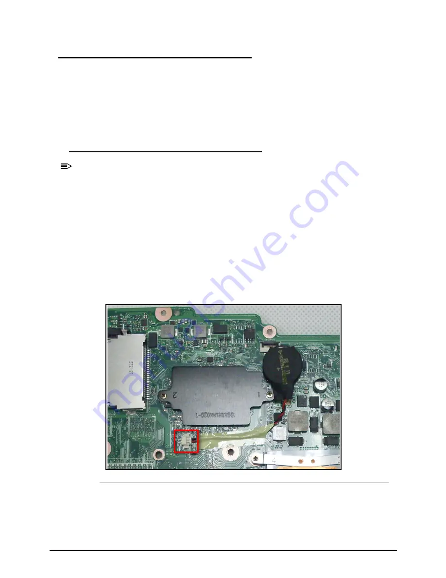
3. Disconnect the RTC Battery (Figure 5-3).
Figure 5-3. RTC Battery
4. Locate the RTCRST# jumper.
5. Use an electric conductivity tool to short the two points of the RTCRST# jumper.
6. Plug in AC, keeping the RTCRST# jumper shorted.
Summary of Contents for TravelMate P453-M
Page 1: ...Acer TravelMate P453 SERVICEGUIDE ...
Page 4: ...iv ...
Page 9: ...ix Introduction 8 3 ...
Page 10: ...x ...
Page 11: ...CHAPTER 1 Hardware Specifications ...
Page 14: ...1 4 ...
Page 57: ...CHAPTER 2 System Utilities ...
Page 67: ...System Utilities 2 11 Figure 2 9 Setup Warning ...
Page 85: ...System Utilities 2 29 Figure 2 37 GU bat ...
Page 88: ...2 32 System Utilities ...
Page 89: ...CHAPTER 3 Machine Maintenance ...
Page 92: ...3 4 ...
Page 99: ...3 11 3 Lift the bottom edge of battery bar first to remove the battery Figure 3 6 Battery ...
Page 101: ...3 13 3 Lift to remove the main door Figure 3 9 Main Door ...
Page 104: ...3 16 5 Remove the HDD bracket Figure 3 14 HDD Bracket ...
Page 107: ...3 19 Figure 3 19 ODD Bracket ...
Page 142: ...3 54 Figure 3 78 LCD Hinge CAUTION Distinguish the left and right hinge before assembling ...
Page 147: ...3 59 Figure 3 86 LCD Bezel ...
Page 158: ...3 70 3 Connect the cable from IO board to motherboard Figure 3 103 IO Board ...
Page 164: ...3 76 Figure 3 113 Top Case Module ...
Page 166: ...3 78 3 Lock 6 latches Esc F4 F8 F12 Del End around the keyboard Figure 3 116 Keyboard ...
Page 178: ...3 90 ...
Page 179: ...CHAPTER 4 Troubleshooting ...
Page 206: ...4 28 Troubleshooting ...
Page 207: ...CHAPTER 5 Jumper and Connector Locations ...
Page 215: ...CHAPTER 6 FRU List ...
Page 216: ...6 2 TravelMate P453 Exploded Diagrams 6 4 Main Assembly 6 4 FRU List 6 6 ...
Page 230: ...6 16 FRU Field Replaceable Unit List ...
Page 231: ...CHAPTER 7 Test Compatible Components ...
Page 232: ...8 2 Microsoft Windows 7 Environment Test 7 4 TravelMate P453 7 4 ...
Page 240: ...7 10 Test Compatible Components ...
Page 241: ...CHAPTER 8 Online Support Information ...
Page 242: ...9 2 Introduction 8 3 ...
Page 244: ...8 4 Online Support Information ...