Acer TravelMate 8481 Service Manual Download Page 108

3-26

Machine Maintenance Procedures

CAUTION

:

!

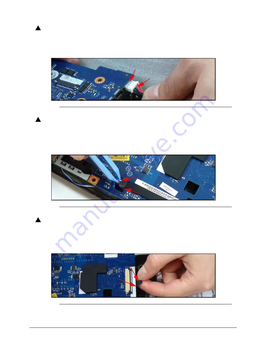
DC-IN cable is attached to mainboard. Use caution when removing mainboard. 

7. Lift mainboard until DC-in cable is clear of lower cover.
8. Disconnect DC-IN cable (N) from mainboard connector (P) as shown in Figure 3-29.

Figure 3-29.

DC-IN Cable

CAUTION

:

!

Speakers cable is attached to mainboard. Use caution when removing 
mainboard. 

9. Disconnect speakers cable (Q) from mainboard connector (R) (not shown) as shown in 

Figure 3-30.

Figure 3-30.

Speakers cable

CAUTION

:

!

Use caution when removing mainboard. HDD module cable is attached to 
mainboard.

10. Disconnect HDD module cable (S) from mainboard connector (T) (not shown) 

(Figure 3-31).

Figure 3-31.

HDD Module Cable

11. Remove mainboard.

N

P

Q

R

S

T

Summary of Contents for TravelMate 8481

Page 1: ...i TravelMate 8481 8481G 8481T 8481TG SERVICE GUIDE ...

Page 2: ...nical magnetic optical chemical manual or otherwise without the prior written permission of Acer Incorporated Disclaimer The information in this guide is subject to change without notice There are no representations or warranties either expressed or implied with respect to the contents hereof and specifically disclaims any warranties of merchantability or fitness for any particular purpose The sof...

Page 3: ... this document Book titles directory names file names path names and program process names are shown in italics Example the DRS5 User s Guide usr local bin fd the TPH15spool_M program Computer output text that represents information displayed on a computer screen such as menus prompts responses to input and error messages are shown in constant width Example 01 The server has been stopped User inpu...

Page 4: ...eneric service guide In such cases contact your regional offices or the responsible personnel channel to provide further technical details When ordering FRU parts Check the most up to date information available on your regional Web or channel If for whatever reason a part number change is made it may not be noted in this printed service guide Acer authorized Service Providers Your Acer office may ...

Page 5: ...ons and Accessories 1 9 System Compliance 1 9 Warranty 1 9 Environment 1 10 Software 1 10 Notebook Tour 1 12 Top View 1 12 Closed Front View 1 14 Left View 1 15 Right View 1 16 Base View 1 17 Touchpad Basics 1 18 Using the Keyboard 1 19 Windows Keys 1 20 Hotkeys 1 21 System Block Diagram 1 23 Specification Tables 1 24 Computer specifications 1 24 System Board Major Chips 1 25 Processor 1 25 Proces...

Page 6: ... 1 35 Battery 1 35 VRAM 1 36 USB Port 1 36 HDMI Port 1 36 eSATA Port 1 36 AC Adapter 1 37 System Power Management 1 37 Card Reader 1 37 System LED Indicator 1 38 System DMA Specification 1 39 System Interrupt Specification 1 40 System IO Address Map 1 41 System IO Address Specifications 1 42 CHAPTER 2 System Utilities BIOS Setup Utility 2 3 Navigating the BIOS Utility 2 3 BIOS 2 4 Information 2 4 ...

Page 7: ...l 3 12 DIMM Module Installation 3 13 Keyboard Removal 3 14 Keyboard Installation 3 16 Upper Cover Removal 3 17 Upper Cover Installation 3 19 MSATA SSD Module Removal 3 21 MSATA SSD Module Installation 3 21 Bluetooth Module Removal 3 22 Bluetooth Module Installation 3 22 Universal Serial Bus USB Module Removal 3 23 USB Module Installation 3 23 WLAN Module Removal 3 24 WLAN Module Installation 3 24 ...

Page 8: ...n 4 3 Power On Issues 4 4 No Display Issues 4 5 LCD Failure 4 7 Keyboard Failure 4 8 Touchpad Failure 4 9 Internal Speaker Failure 4 10 Microphone Failure 4 12 USB Failure 4 13 Wireless Function Failure 4 14 Bluetooth Failure 4 15 Thermal Unit Failure 4 16 MSATA SDD test Failure 4 17 Cosmetic Failure 4 18 Other Functions Failure 4 19 Intermittent Problems 4 21 Undetermined Problems 4 21 Post Codes...

Page 9: ...14 CHAPTER 7 Model Definition and Configuration TravelMate 8481 7 3 TravelMate 8481G 7 11 TravelMate 8481T 7 14 TravelMate 8481TG 7 35 CHAPTER 8 Test Compatible Components Microsoft Windows 7 Environment Test 8 4 TravelMate 8481 8481G 8481T 8481TG 8 4 CHAPTER 9 Online Support Information Introduction 9 3 ...

Page 10: ...vi ...

Page 11: ...CHAPTER 1 Hardware Specification ...

Page 12: ...9 Environment 1 10 Software 1 10 Notebook Tour 1 12 Top View 1 12 Closed Front View 1 14 Left View 1 15 Right View 1 16 Base View 1 17 Touchpad Basics 1 18 Using the Keyboard 1 19 Windows Keys 1 20 Hotkeys 1 21 System Block Diagram 1 23 Specification Tables 1 24 Computer specifications 1 24 System Board Major Chips 1 25 Processor 1 25 Processor Specifications Taken from FRU 1 26 CPU Fan True Value...

Page 13: ...le 1 33 Camera 1 33 Mini Card 1 34 Audio Codec and Amplifier 1 34 Audio Interface 1 35 Wireless Module 802 11b g n 1 35 Battery 1 35 VRAM 1 36 USB Port 1 36 HDMI Port 1 36 eSATA Port 1 36 AC Adapter 1 37 System Power Management 1 37 Card Reader 1 37 System LED Indicator 1 38 System DMA Specification 1 39 System Interrupt Specification 1 40 System IO Address Map 1 41 System IO Address Specification...

Page 14: ...1 4 ...

Page 15: ...ache Intel Core i5 2467M i5 2557M processor 3 MB L3 cache 1 60 1 70 GHz with Turbo Boost up to 2 70 GHz DDR3 1333 MHz 17 W supporting Intel 64 architecture Intel Smart Cache Mobile Intel UM67 Express Chipset Memory 0 Dual channel DDR3 SDRAM support Up to 4 GB of DDR3 system memory upgradable to 8 GB using two soDIMM modules for 64 bit OS Up to 2 GB of DDR3 system memory upgradable to 4 GB using tw...

Page 16: ... up to 40952 MB of TurboCache 1024 MB of dedicated DDR3 VRAM up to 3071 MB of shared system memory supporting Storage 0 Hard disk drive 250 320 GB or larger with enhanced Acer DASP Disk Anti Shock Protection Solid state drive 128 GB or larger 64 GB or larger with mini SATA mSATA interface connector for models with mSATA only Multi in 1 card reader supporting Secure Digital SD Card MultiMediaCard M...

Page 17: ...rprint solution featuring Pre Boot Authentication PBA computer protection Trusted Platform Module TPM solution BIOS user supervisor HDD passwords Kensington lock slot Dimensions and Weight 0 Dimensions 328 7 W x 239 9 D x 18 22 3 H mm 12 94 x 9 44 x 0 7 0 87 inches Weight 1 7 kg 3 747 lbs with 8 cell battery pack TravelMate 8481 8481G 0 1 5 kg 3 306 lbs with 4 cell battery pack Power Adapter and B...

Page 18: ...urs TravelMate 8481TG 0 87 Wh 6000 mAh 8 cell Li ion battery pack Battery life 9 hours Input and Control 0 Keyboard 86 88 91 key Acer FineTouch keyboard with international language support Touchpad Next generation oversized multi gesture touchpad featuring three finger press flip and swipe in addition to two finger scroll pinch and rotate Media keys Media control keys printed on keyboard play paus...

Page 19: ...rnet RJ 45 port DC in jack for AC adapter Options and Accessories 0 1 2 4 GB DDR3 soDIMM module 250 320 GB hard disk drive 8 cell Li ion 6000 mAh battery pack USB optical genius mini mouse 3 pin 65 W AC adapter TravelMate 8481 8481G 8481TG 0 4 cell Li ion 2960 mAh battery pack System Compliance 0 Wi Fi ACPI 3 0 Mobile PC 2002 DMI 2 0 ENERGY STAR EPEAT Silver TravelMate 8481G 8481TG 0 HSF Need upda...

Page 20: ... Adobe Flash Player 10 1 Adobe Reader 9 1 Bing Bar NewsXpresso Microsoft Office 2010 preloaded purchase a product key to activate Microsoft Office Starter 2010 Norton Online Backup Security Acer Proshield Absolute Data Protect EMEA PA only McAfee Internet Security Suite Trial InstantOn InstantView Multimedia Corel WinDVD NTI Media Maker Communication and ISP Acer Crystal Eye Acer Video Conference ...

Page 21: ... Acer Accessory Store Belgium France Germany Italy Netherlands Spain Sweden UK only Acer Identity Card Acer Registration Acer Updater eBay shortcut 2009 Canada France Germany Italy Mexico Spain UK US only Netflix shortcut1 US only ...

Page 22: ...rated webcam Web camera for video communication only for certain models 2 Display screen Also called Liquid Crystal Display LCD displays computer output Configuration may vary by models 3 Microphone Internal microphone for sound recording 4 Keyboard For entering data into your computer 1 2 3 4 5 6 7 8 9 ...

Page 23: ...our computer into power saving mode configuration may vary by model P key Programmable key configuration may vary by model Acer InstantView Opens the Acer InstantView application Backup key Launches Acer Backup Management for three step data backup Microphone mute Mutes the microphone Power button indicator Turns the computer on and off Indicates the computer s power status 9 Num Lock Lights up wh...

Page 24: ...rd can operate at any given time 2 Power indicator Indicates the computer s power status Battery indicator Indicates the computer s battery status Charging The light shows amber when the battery is charging Fully charged The light shows blue when in AC mode HDD indicator Indicates when the hard disk drive is active 3 Communication switch indicator Enables disables the computer s communication devi...

Page 25: ...ctions 4 USB 2 0 eSATA port Connects to USB 2 0 or eSATA devices only for certain models NOTE If you plug in an eSATA device you will have three USB ports available 5 USB 3 0 port Connects to USB devices A USB 3 0 port can be distinguished by its blue connector 6 Microphone jack Accepts inputs from external microphones Headphones speaker jack Connects to audio devices e g speakers headphones NOTE ...

Page 26: ...era 2 Kensington lock slot Connects to a Kensington compatible computer security lock NOTE Wrap the computer security lock cable around an immovable object such as a table or handle of a locked drawer Insert the lock into the notch and turn the key to secure the lock Some keyless models are also available 3 DC in jack Connects to an AC adapter 1 2 3 ...

Page 27: ...k 2 Battery lock Locks the battery in position 3 Hard disk bay Houses the computer s hard disk secured with screws 4 Speakers Emit stereo sound 5 Memory compartment Houses the computer s main memory 6 Battery release latch lock Releases the battery for removal Insert a suitable tool into the latch and slide to release 1 2 3 4 5 6 ...

Page 28: ...tton 2 Left Button 3 Execute Tap twice at the same speed as double clicking a mouse button Quickly click twice Select Tap once Click once Drag Tap twice at the same speed as double clicking a mouse button rest your finger on the TouchPad on the second tap and drag the cursor Click and hold then use finger on the Touchpad to drag the cursor Access context menu Click once NOTE When using the TouchPa...

Page 29: ...d keypad is in numeric mode The keys function as a calculator complete with the arithmetic operators and Use this mode when doing a lot of numeric data entry A better solution would be to connect an external keypad Scroll Lock Fn F12 When Scroll Lock is on the screen moves one line up or down when the up or down arrow keys are pressed respectively Scroll Lock does not work with some applications T...

Page 30: ...dow E Open Windows Explorer F Search for a file or folder D Show the desktop CTRL F Search for computers if you are on a network L Lock your computer if you are connected to a network domain or switch users if you re not connected to a network domain CTRL TAB Moves focus from Start menu to the Quick Launch toolbar to the system tray use RIGHT ARROW or LEFT ARROW to move focus to items on the Quick...

Page 31: ...on Function Description Fn F3 Communication switch Enables disables the computer s communication devices Communication devices may vary by configuration Fn F4 Sleep Puts the computer in Sleep mode Fn F5 Display toggle Switches display output between the display screen external monitor if connected and both Fn F6 Screen blank Turns the display screen backlight off to save power Press any key to ret...

Page 32: ...own Decreases audio volume Fn Home Play Pause Plays or pauses media files Fn PgUp Stop Stops media file Fn PgDn Previous Plays the previous media file in the play sequence Fn End Next Plays the next media file in the play sequence Alt F10 D2D Recovery Enter D2D recovery during POST Table 1 10 Keyboard Hotkeys Continued Hotkey Icon Function Description ...

Page 33: ...J45 204pin DDRIII SO DIMM X2 Intel SPI ROM 1 5V DDRIII 1066 1333 HDA Codec Memory BUS DDRIII PCH HD Audio Cougar Point M ENE KB930 BGA1023 Intel Bluetooth Conn port 0 SATA HDD Conn SPI ROM x1 USBx14 port 4 eSATA Conn Int Speaker Headphone Jack x1 USB port 0 1 on USB B 989pin BGA PCI E 2 0x16 5GT s PER LANE 100MHz 133MHz Nvidia N12P GV PEG DIS HDMI Conn NEC uPD720200AF1 port 5 VGA VGA ULV USB port ...

Page 34: ...Temperature Operating not writing to optical disc 0 C to 35 C 32 F to 95 F Operating writing to optical disc 5 C to 35 C 41 F to 95 F Nonoperating 20 C to 60 C 4 F to 140 F Relative humidity Operating 10 to 90 Nonoperating 5 to 95 Maximum altitude unpressurized Operating 15 m to 3 048 m 50 ft to 10 000 ft Nonoperating 15 m to 12 192 m 50 ft to 40 000 ft Shock Operating Amplitude 150G w o resonance...

Page 35: ... Broadcom BCM2070 Wireless Atheros T77H167 07 Broadcom T77H268 00 LITE ON WN6603AH AA Intel 62205AN HMWG Audio codec Realtek ALC271 X Card reader Realtek RTS 5209 GR Item Specification CPU type Intel Core i3 i5 i7 Processor CPU package BGA1023 Core Logic Four or two execution cores A 32 KB instruction and 32 KB data first level cache L1 for each core A 256 KB shared instruction data second level c...

Page 36: ...GHz 2 Cores 5GT s 32 nm 4 MB BGA1023 0 7 1 2V CPU Temperature Fan Speed RPM SPL Spec dBA 45 3400 28 50 3900 31 55 4500 34 60 5100 37 65 5200 38 5 70 5200 38 5 Throttling 50 On 99 C OFF 95 C OS shut down at 100 C H W shut down at 92 C Item Specification Memory controller Built in on CPU Memory size 1GB 2GB 4GB DDR3 RAM DIMM socket number 2 Supports memory size per socket 2 GB 32 bit OS 4 GB 64 bit ...

Page 37: ...4 2048 3072 1024 4096 5120 2048 0 2048 2048 1024 3072 2048 2048 4096 2048 4096 6144 4096 0 4096 4096 1024 5120 4096 2048 6144 4096 4096 8192 Item Specification Chipset NVIDIA N12P GV Package 29 x 29 mm 973 ball FCBGA Interface PCI Express 2 0 x 16 Compatibility N A Sampling rate PCI E 2 0 traffic for a peak bandwidth of up to 20 GB per second ...

Page 38: ...Various hot keys for system control Support SMBIOS 2 3 PCI 2 2 DMI utility for BIOS serial number configurable asset tag Support PXE Support WinFlash Wake on LAN from S3 Wake on LAN from S5 in AC mode System information HDD password Anti theft support Computrace Refer to Acer BIOS specification Item Specification LAN Chipset BCM57761B0KMLG LAN connector type RJ45 No LED LAN connector location RJ45...

Page 39: ...igurable different languages by OEM customer Item Specification Vendor Model Name HTS543225A7A 384 HTS543232A7A 384 ST250LT003 ST320LT020 Capacity GB 250 320 250 320 Bytes per sector 512 512 4096 4096 Data heads 2 2 2 2 Drive Format Disks 1 1 1 1 Spindle speed RPM 5400 Performance Specifications Buffer size 8MB Interface SATA Fast data transfer rate Gbits sec max 3 0 3 0 3 0 3 0 Media data transfe...

Page 40: ...er size 16MB Interface SATA Fast data transfer rate Gbits sec max 3 0 3 0 3 0 3 0 Media data transfer rate Mbytes sec max 166 75 166 75 155 9 155 9 DC Power Requirements Voltage tolerance 5V Item Specification Vendor Model name Performance Specification Transfer rate KB sec Buffer Memory Interface Applicable disc format Loading mechanism Power Requirement Input Voltage Item Specification ...

Page 41: ...18 mm Typ with PCB Display resolution pixels 1366 x 3 RGB x 768 Pixel Pitch mm 0 2265mm 0 2265 mm Typical White Luminance cd m2 also called Brightness 200 cd m2 Contrast Ratio 400 min 500 type Response Time Optical Rise Time Fall Time msec 16 ms 25 ms Typical Power Consumption watt 3 49W Weight without inverter 190g max Physical Size mm 322 2 mm x 198 88 mm x 1 27 max Electrical Interface 1 channe...

Page 42: ...ge V RMS 4 5V to 38V Output current mA RMS 19 4mA to 20 6mA Output voltage frequency KHz 0 1 KHz to1 KHz Resolution 16 bits 32 bits 800x600p 60Hz 16 9 V V 1024x768p 60Hz 16 9 V V 1280x600 60Hz 16 9 V V 1280x720 60Hz 16 9 V V 1280x768 60Hz 16 9 V V 1360x768 60Hz 16 9 V V 1366x768 60Hz 16 9 V V Item Specification VGA Chip VGA SKU NVIDIA N12P GV FCBGA 973P UMA SKU N A Output by INTEL PCH Supports VGA...

Page 43: ...0Hz 16 9 V V V V 1366x768 60Hz 16 9 V V V V Item Specifications Chipset Broadcom BCM2070 Atheros BU12 Data throughput TX 1 2Mbits sec RX 1 2Mbits sec Protocol 3 0 HS Interface USB 2 0 Connector type SM06B XSRK ETB Supported protocol A2DP Item Specifications Controller Foxconn_ T77H114 01 Broadcomm_BCM2070 Foxconn_ T77H222 01 Atheros_ AR3011 Features Mini USB module with built in antenna Bluetooth ...

Page 44: ...rts external PCBEEP input and built in digital BEEP generator Software selectable 2 5V 3 2V VREFOUT as bias voltage for analog microphone input Programmable 12 24 36dB boost gain for analog microphone input Supports stereo digital microphone input Programmable boost gain and volume control for digital microphone input Built in headphone amplifiers for port C LINE1 and port I HP OUT Headphone ampli...

Page 45: ... Internal speaker quantity Yes 2W speakers x2 Item Specification Chipset FOXCONN Atheros _T77H167 07 LITE ON Atheros _ WN6603AH AA Foxconn Broadcom _T77H268 00 Intel_ Centrino Advanced N 6205 Taylor Peak Data throughput 802 11b 11Mbps max 802 11g 54Mbps max 802 11n 300Mbps max Protocol IEEE 802 11b g n Interface PCI Express interface Standard mini card Item Specification Vendor Model name SANYO AS...

Page 46: ...ion USB compliance level USB 2 0 USB3 0 USB3 0 also supports USB 2 0 device EHCI Meet USB IF support EHCI UHCI for 2 0 xHCI for 3 0 Number of USB port s 3 ports for USB2 0 1port for USB3 0 Location 2 ports at right side 2 ports at left side Output Current 2 0A each port except right side they are shared Item Specification Compliance level HDMI v1 4 Data thoroughput Up to 16 7 million colors Number...

Page 47: ...xcept for the logic required to restart A full boot is required when waking Working G0 S0 Full On Processor operating Individual devices may be shut down or be placed into lower power states to save power Suspend to RAM S3 Suspend To RAM STR The system context is maintained in system DRAM but power is shut off to non critical circuits Memory is retained and refreshes continue All external clocks s...

Page 48: ...reeze mode Orange 1 sec on 3 sec off Battery critical low less than 3 or abnormal battery situation Blinking mode Orange 1 sec on 1 sec off Using battery or not connected to AC power N A Communication device state Orange WiFi only Orange Both off N A WiMax is the same as WiFi behavior Mute Mic button Mute Blue color Unmute no color Backup key button Blue color Default LED is off Press button LED w...

Page 49: ...Power Management DMA0 Not applicable DMA1 Not applicable DMA2 Not applicable DMA3 Not applicable DMA4 Direct memory access controller DMA5 Available for ExpressCard DMA6 Not Assigned DMA7 Not Assigned ExpressCard controller can use DMA 1 2 or 5 ...

Page 50: ...ck IRQ8 System timer IRQ9 Microsoft ACPI compliant system IRQ10 VGA compatible controller Communication controller EHCI USB controller 1C2D SD Host controller IRQ11 HD Audio controller EHCI USB controller 1C26 IRQ12 Synaptics PS 2 TouchPad IRQ13 Numeric data processor IRQ14 Primary IDE channel IRQ15 Secondary IDE channel Default configuration audio possible configurations are IRQ5 IRQ7 IRQ9 IRQ10 ...

Page 51: ...0060 0060 Standard PS 2 keyboard 0061 0061 Motherboard resources 0062 0062 Microsoft ACPI Compliant Embedded Controller 0063 0063 Motherboard resources 0064 0064 Standard PS 2 keyboard 0065 0065 Motherboard resources 0066 0066 Microsoft ACPI Compliant Embedded Controller 0067 0067 Motherboard resources 0068 0068 Motherboard resources 006C 006C Motherboard resources 0070 0070 Motherboard resources ...

Page 52: ...F Motherboard resources 0680 069F Motherboard resources 0D00 FFFF PCI bus 1000 100F Motherboard resources 164E 164F Motherboard resources 2000 2FFF 2nd generation Intel core processor family PCI Express Controller 0101 2F80 2FFF NVIDIA Geforce GT520M 3000 303F Intel HD Graphics Family 3040 305F Intel SMBus controller 1C22 3060 307F Intel Mobile Express Chipset SATA AHCI controller 3090 3097 Intel ...

Page 53: ...CHAPTER 2 System Utilities ...

Page 54: ...2 14 Exit 2 15 BIOS Flash Utilities 2 16 DOS Flash Utility 2 17 WinFlash Utility 2 19 HDD BIOS Password Utilities 2 22 Clearing HDD Passwords 2 22 Clearing BIOS Passwords 2 24 Miscellaneous Tools 2 26 Using Boot Sequence Selector 2 26 Using Boot Manager 2 27 Using DMITools 2 28 Using LAN MAC EEPROM Utility 2 30 ...

Page 55: ...e parameter to Enabled To change the boot device without entering the BIOS SETUP press F12 during POST to enter the multi boot menu Navigating the BIOS Utility 0 Five menu options are Information Main Security Boot Exit To navigate through the following Menu use the left and right arrow keys Item use the up and down arrow keys Change parameter value press F5 or F6 Exit Press Esc Load default setti...

Page 56: ...20 Setup Utility Rev 3 5 Information Main Security Boot Exit CPU Type Intel R Core TM 2 Duo CPU T7300 CPU Speed 2 00GHz HDD Model Name ST960821A PM HDD Serial Number 3LF005DB ATAPI Model Name MATSHITADVD System BIOS Version V1 05 VGA BIOS Version ATI V008 050I 0 26 00 Serial Number xxxxxxxxxxxxxxxxxxxx Max 22 Byte Asset Tag Number xxxxxxxxxxxxxxxxxxxx Max 32 Byte Product Name xxxxxxxxxxxxxxxxxxxx ...

Page 57: ...n primary IDE master HDD Serial Number Serial number of HDD0 installed on primary IDE master ATAPI Model Name Model name of Optical device installed in system System BIOS Version System BIOS version VGA BIOS Version VGA video graphics array firmware version of system Serial Number Serial number of unit Asset Tag Number Asset tag number of system Product Name Product name of the system UUID Univers...

Page 58: ...1 2003 Total Memory xxxx MB Video Memory xMB Graphic mode Switchable Quiet Boot Enabled Network Boot Enabled F12 Boot Menu Disabled D2D Recovery Enabled SATA Mode AHCI Mode Function key behavior Special keys Wi Fi Enabled Bluetooth Enabled 3G Disabled Card Reader Enabled USB ports Enabled Wired Lan Enabled Audio Disabled Camera Enabled Power off USB Charge Enabled Battery Threshold 20 ASF Configur...

Page 59: ...d or Disabled SATA Mode Option to set SATA controller mode Option AHCI or IDE Function key behavior Press Fn F1 Fn F2 Fn F12 to activate specific function keys Wi Fi Option to use Wi Fi device Option Enabled or Disabled Bluetooth Option to use Bluetooth device Option Enabled or Disabled 3G Option to use 3G device Option Enabled or Disabled Card Reader Option to use card reader Option Enabled or Di...

Page 60: ... HDD Password Is Clear Set Supervisor Password Enter Set User Password Enter Set HDD Password Enter Password on Boot Disabled Current TPM State Change TPM State No Change F1 Help Select Item F5 F6 Change Values F9 Setup Default ESC Exit Select Menu Enter Select SubMenu F10 Save and Exit Table 2 3 BIOS Security Parameter Description Option Supervisor Password Is Supervisor password setting Clear or...

Page 61: ...TE NOTE To change an existing password refer to Clearing Password Figure 2 4 Setting a Password Set Supervisor Password 2 Type a new password in the Enter New Password field and press Enter Password on Boot CAUTION If Power on Password authentication is enabled the BIOS password can only be cleared by initiating the Crisis Disk Recovery procedure Refer to BIOS Recovery by Crisis Disk Shows if pass...

Page 62: ...p Notice dialog screen is shown Figure 2 5 If it is not go to step 5 Figure 2 5 Setting a Password Confirmation Notice a Press Enter to return to the BIOS Setup Utility Security menu b The Supervisor Password parameter is shown as Set c Press F10 to save changes and exit BIOS Setup Utility A Z Alphabets A through Z Not Case Sensitive 0 9 Numerical Characters Dash Equal Sign Left Bracket Right Brac...

Page 63: ...ighlight Set Supervisor Password and press Enter The Set Supervisor Password dialog box is shown Figure 2 7 Figure 2 7 Removing a Password Set Supervisor Password 2 Type current password in Enter Current Password field and press Enter 3 Press Enter twice without typing anything in Enter New Password and Confirm New Password fields Computer will set Supervisor Password parameter to Clear 4 Press F1...

Page 64: ...ce dialog is shown Figure 2 9 If it is not shown go to step 6 Figure 2 9 Changing a Password Setup Notice a Press Enter to return to the BIOS Setup Utility Security menu b The Supervisor Password parameter is shown as Set c Press F10 to save changes and exit BIOS Setup Utility 6 If current password and new password strings do not match the Setup Warning dialog is shown Figure 2 10 If it is not sho...

Page 65: ...w password and confirm new password strings do not match the Setup Warning dialog is shown Figure 2 11 Figure 2 11 Changing a Password Passwords Do Not Match a Press Enter to return to the BIOS Setup Utility Security menu b The Supervisor Password parameter is shown as Clear c To try to change the password again repeat steps 1 through 4 Setup Warning Passwords do not match Re enter password Contin...

Page 66: ...e the value Figure 2 12 BIOS Boot InsydeH20 Setup Utility Rev 3 5 Information Main Security Boot Exit Item Specific Help Boot priority order Use or to select a device then press F6 to move it up the list or F5 to move it down the list Press Esc to escape the menu 1 IDE0 ST960821A 2 IDE1 MATSHITADVD 3 USB FDD 4 Network Boot Realtek Boot Agent 5 USB HDD 6 USB CDROM F1 Help Select Item F5 F6 Change V...

Page 67: ... values for all SETUP item Exit Discard Changes Load Setup Defaults Discard Changes Save Changes F1 Help Select Item F5 F6 Change Values F9 Setup Default ESC Exit Select Menu Enter Select SubMenu F10 Save and Exit Table 2 4 Exit Parameters Parameter Description Exit Saving Changes Exit BIOS utility and save setup item changes to system Exit Discarding Changes Exit BIOS utility without saving setup...

Page 68: ...ate one before BIOS Flash utility is used Refer to BIOS Recovery by Crisis Disk NOTE NOTE Do not install memory related drivers XMS EMS DPMI when BIOS Flash is used NOTE NOTE Use AC adaptor power supply when running BIOS Flash utility If battery pack does not contain power to finish loading BIOS Flash do not boot system Perform the following to run BIOS Flash 1 Prepare a bootable USB HDD 2 Copy Fl...

Page 69: ...DD 5 Insert the USB HDD and reboot computer 6 Execute BIOS BAT to update BIOS Figure 2 17 Figure 2 15 Executing BIOS BAT InsydeH20 Setup Utility Rev 3 5 Information Main Security Boot Exit Item Specific Help Boot priority order Use or to select a device then press F6 to move it up the list or F5 to move it down the list Press Esc to escape the menu 1 IDE0 ST960821A 2 IDE1 MATSHITADVD 3 USB FDD 4 N...

Page 70: ... Nick 01 Only Support SPI Nov 04 2009 15 49 40 Create by LJC Modify by Ja Fer Ray V1 9 7 File Name KBCA100A ROM file size 0x1C792 Bytes Start Loading flash ROM Loading Loading flash ROM completed SB Intel Turn On Fan KBC ID 3926 0K 12K 12K 16K 120K 128K 128K 136K is skipped KBC Idle Checking Flash Manufacture ID and Device ID method 1 MID c2 DID 10 Mx25l1005 MID 0xC2 DID 0x10 Flash Size 0x20000 by...

Page 71: ...older Figure 2 19 Figure 2 19 Winflash Program Folder NOTE NOTE Flashing of system BIOS cannot be performed on battery power Make sure AC adapter is connecting to device before executing program 3 Double click the WinFlash executable 4 Click OK to begin the update Figure 2 20 Figure 2 20 Executing Winflash Program 1 of 2 ...

Page 72: ...ress screen is shown Figure 2 21 Figure 2 21 InsydeFlash 2 of 2 6 After flashing process is complete the program will automatically restart the system 7 If AC adapter is not connected the following dialogs are shown Figure 2 22 Figure 2 23 Figure 2 22 No AC Power Detected 1 of 2 P4VC0 P4VC0 V1 03 V1 05 ...

Page 73: ... Figure 2 23 No AC Power Detected 2 of 2 8 Connect AC adapter to device and repeat steps two through four 9 If there is BIOS ROM file size error the following dialog is shown Figure 2 24 Figure 2 24 BIOS ROM File Size Error ...

Page 74: ...rrectly entered three times an error is generated Figure 2 25 Figure 2 25 Password Error Status Dialog To reset the HDD password perform the following 1 Press Enter to continue The Select Item dialog is shown Figure 2 26 Figure 2 26 Select Item Dialog 2 Use the and keys to highlight Enter Unlock Password and press Enter The Enter Unlock Password dialog is shown Figure 2 27 Figure 2 27 Enter Unlock...

Page 75: ... a password unlock code Use the format UnlockHD key code with the code noted in the Figure 2 27 Example UnlockHD 54591747 The command generates a password which can be used for unlocking the HDD Password 41499389 Figure 2 28 Unlock Password 5 On original device enter password Figure 2 28 in Enter Unlock Password dialog Figure 2 29 Figure 2 29 Unlock Password Dialog Enter Unlock Password Key 545917...

Page 76: ... clearing the BIOS password A hardware method and a software method Hardware Method 0 1 Remove AC adapter 2 Short CMOS jumper point A Figure 2 30 Figure 2 30 CMOS Jumper 3 Plug in AC adapter 4 Restart the system and press F2 to enter BIOS Utility Setup menu 5 If no password prompt is shown BIOS password is cleared 6 If password prompt is shown repeat steps 1 through 5 Table 2 5 CMOS Jumper Item De...

Page 77: ...lean the desired password Figure 2 31 Figure 2 31 Clean BIOS Password 3 The on screen message shows function success or failure D Clnpwd clnpwd Acer Clean Password Utility V1 00 Press 1 or 2 to clean any password shown as below 1 User Password 2 Supervisor Password Clean User Password Successful ...

Page 78: ... At a DOS prompt enter bs and a boot sequence ID number A boot sequence ID is a digit from 1 to 4 Figure 2 32 Boot Sequence Selector Example bs 2 selects the boot sequence of HDD CD ROM LAN Floppy D BOOTSEQ bs Boot Sequence Selector Version 0 03 Created by Rockwell Chuang 10 01 2005 Usage BS 1 2 3 4 BS 1 Floppy HardDisk CD ROM LAN BS 2 HardDisk CD ROM LAN Floppy BS 3 CD ROM HardDisk LAN Floppy BS ...

Page 79: ...fer to Main To use the Boot Manager perform the following steps 1 Start the computer 2 Press F12 when prompted during POST procedure The Boot Manager dialog is shown Figure 2 33 Figure 2 33 Boot Manager Dialog 3 Use the and keys to highlight a boot device 4 Press Enter to select an option and continue the boot procedure Boot Manager Boot Option Menu 1 IDE 0 Hitachixxxxxxxx 2 IDE 1 Optiarc DVD RW x...

Page 80: ... memory wm Write Manufacturer Name to EEPROM max 16 characters wp Write Product Name to EEPROM max 20 characters ws Write Serial Number to EEPROM max 22 characters wu Write UUID to EEPROM ignore string wa Write Asset Tag to EEPROM max 32 characters The following examples show the commands and the corresponding output information Read DMI Information from Memory Input 0 dmitools r Output 0 Manufact...

Page 81: ...D to EEPROM Create UUID from Intel WFM20 pdf Input 0 dmitools wu Write Asset Tag to EEPROM Input 0 dmitools wa Acer Asstag NOTE NOTE For examples two 2 through five 5 restart the system to write any changes in the data to the EEPROM ...

Page 82: ...hen process has completed To write MAC Media Access Control information to EEPROM perform the following 1 Start computer and press F2 during boot sequence to enter Setup Menu 2 Select Boot menu to modify boot priority order 3 Insert USB HDD and reboot computer 4 Execute MAC BAT xxxxxx where xxxxxx is a 6 character MAC address to write the MAC information to EEPROM Table 2 6 MAC cfg Field Names Val...

Page 83: ...CHAPTER 3 Machine Maintenance ...

Page 84: ...ule Installation 3 22 Universal Serial Bus USB Module Removal 3 23 USB Module Installation 3 23 WLAN Module Removal 3 24 WLAN Module Installation 3 24 Mainboard Removal 3 25 Mainboard Installation 3 27 RTC Battery Removal 3 28 RTC Battery Installation 3 28 FAN Module Removal 3 29 FAN Module Installation 3 29 Thermal Module Assembly Removal 3 30 Thermal Module Assembly Installation 3 31 Speakers Re...

Page 85: ... following procedures may not represent the final product color or configuration Cable paths and positioning may also differ from the actual model During the removal and installation of components make sure all available cable channels and clips are used and that the cables are installed in the same position All prerequisites must be performed prior to performing maintenance Recommended Equipment ...

Page 86: ...ontains a complete list of the required screws and fasteners required when performing any maintenance on the notebook computer Table 3 1 Main Screw List Screw Quantity M2 0x2 5 BNZ 11 M2 5x4 0 ZK 17 M2 0x10 ZK 2 M2 5x5 0 ZK 21 M2 0x4 0 NI 3 M2 0x3 0 4 M2 5x3 0 4 ...

Page 87: ...ce Flowchart 0 The flowchart in Figure 3 1 provides a graphic representation of the module removal and installation sequences It provides information on what components need to be removed and installed during servicing Figure 3 1 Maintenance Flow ...

Page 88: ...l and install sequence Observe the order of the sequence to avoid damage to any of the hardware components Perform the following prior to performing any maintenance procedures 1 Remove power A from the system and peripherals Figure 3 2 2 Remove all cables from system Figure 3 2 AC Adapter 3 Place system on a stable work surface A ...

Page 89: ...ease latch B to release position 4 Remove battery pack C and release latch B Figure 3 3 Battery Pack IMPORTANT Follow local regulations for battery disposal Figure 3 3 Battery Pack Installation 0 1 Align battery cover to slots D on lower cover and press to secure Figure 3 4 Lower Cover Slots 2 Slide battery lock A into lock position Figure 3 3 A C B E E E E E D ...

Page 90: ...3 8 Machine Maintenance Procedures Dummy Card Removal 0 1 Push in dummy card A to release 2 Remove card A Figure 3 5 Dummy Card Dummy Card Installation 0 1 Install dummy card A 2 Push in to lock A ...

Page 91: ...ws A from HDD module door B Figure 3 6 2 Use tab C to remove door from lower cover Figure 3 6 Figure 3 6 HDD Module CAUTION HDD module is attached to mainboard by HDD cable Use caution when removing HDD module 3 Insert tool to opening D Lift module E in an angle to access HDD cable Figure 3 7 Figure 3 7 HDD Module D A B C D E ...

Page 92: ...Cable 5 Starting from rubber tabs G remove HDD module from rubber covering Figure 3 9 Figure 3 9 Removing HDD Module from Rubber Covering HDD Module Installation 0 1 Install module E into rubber covering G Figure 3 9 2 Connect cable F to module connector J Figure 3 8 3 Install module into bay Figure 3 7 F J G E ...

Page 93: ...3 11 4 Align door B to slots H on lower cover and install Figure 3 10 Figure 3 10 Installing HDD Module Door 5 Install and secure two 2 screws A on module Figure 3 6 6 Install battery pack ID Size Quantity Screw Type A M2 5x3 0 2 H B ...

Page 94: ... 2 screws A from module door B Figure 3 11 2 Use tab C to remove door B from lower cover Figure 3 11 Figure 3 11 DIMM Modules Door 3 Open module clips E to unlock module Figure 3 12 4 Slide module D from mainboard connector F Figure 3 12 Figure 3 12 DIMM Modules 5 Repeat steps 3 and 4 for remaining DIMM modules A C B D E F F ...

Page 95: ...12 2 Press on DIMM module D until clips E lock in place Figure 3 12 3 Align door B to slots G on lower cover Figure 3 13 Figure 3 13 DIMM Module Door installation 4 Install door B Figure 3 13 5 Install and secure two 2 screws A to door B Figure 3 11 6 Install battery pack ID Size Quantity Screw Type A M2 5x3 0 2 G B ...

Page 96: ...emoval 0 Prerequisite Battery Pack Removal 1 Remove three 3 screws A from lower cover Figure 3 14 Figure 3 14 Lower Cover 2 Place computer face up 3 Locate 7 keyboard locks B as shown in Figure 3 15 Figure 3 15 Keyboard Locks A B B B B B B B B B B ...

Page 97: ...locking Keyboard Locks CAUTION Keyboard is attached to mainboard by Flexible Printed Circuits FPC cable Use caution when removing keyboard 5 Move keyboard to allow access to FPC cable C Figure 3 17 6 Disconnect cable C from mainboard connector D Figure 3 17 Figure 3 17 Keyboard 7 Remove keyboard C D ...

Page 98: ...D Figure 3 17 3 Align bottom edge of keyboard with palmrest Figure 3 18 4 Install 5 keyboard flanges E into slots on upper cover Figure 3 18 Figure 3 18 Keyboard 5 Press to secure to upper cover 6 Place computer face down 7 Install and secure three 3 screws A on lower cover Figure 3 14 8 Install battery pack ID Size Quantity Screw Type A M2 5x5 0 3 E ...

Page 99: ... Prerequisite Keyboard Removal 1 Place computer face down 2 Remove the following screws Figure 3 19 Thirteen 13 screws B from lower cover Two 2 screws C from lower cover Three 3 screws D from batter bay Figure 3 19 Lower Cover 3 Place computer face up B B C D ...

Page 100: ...rom mainboard connector H Function board cable J from mainboard connector K Figure 3 20 Upper Cover 5 Remove five 5 screws A from upper cover Figure 3 20 6 Starting at card reader slot M release all latches to separate upper cover from lower cover Move along edges until upper cover is completely separated from lower cover Figure 3 21 Figure 3 21 Upper Cover E F G H J K A A A M ...

Page 101: ...hone set cable N to mainboard connector P Figure 3 22 3 Install upper cover on lower cover 4 Press along edges to secure all latches 5 Install and secure five 5 screws A to upper cover Figure 3 20 6 Connect the following cables Figure 3 20 Fingerprint board FFC cable E to mainboard connector F Touchpad button assembly FFC cable G to mainboard connector H Function board cable J to mainboard connect...

Page 102: ...3 20 Machine Maintenance Procedures ID Size Quantity Screw Type A B M2 5x5 0 18 C M2 0x10 2 D M2 0x4 0 3 ...

Page 103: ...emoval 1 Locate module A on lower cover 2 Remove screw B from module 3 Disconnect module A from mainboard connector C Figure 3 23 mSATA SSD Module 4 Remove module MSATA SSD Module Installation 0 1 Align and install module A to lower cover 2 Connect module to mainboard connector C not shown 3 Install and secure screw B to module 4 Install upper cover ID Size Quantity Screw Type B M2 0x2 5 1 A B C ...

Page 104: ...n lower cover 2 Disconnect cable B from USB module connector C Figure 3 24 Bluetooth Module 3 Release module from adhesive 4 Remove module Bluetooth Module Installation 0 1 Align module A to lower cover 2 Attach module to adhesive on lower cover 3 Connect cable B to USB module connector C 4 Install upper cover A B C ...

Page 105: ...E 3 Remove screw F from module 4 Disconnect Bluetooth module cable B from connector C Figure 3 25 USB Module 5 Remove module from lower cover USB Module Installation 0 1 Align module A with pins G on lower cover 2 Install module 3 Connect FFC cable D to mainboard connector E 4 Install and secure screw F to module A 5 Install upper cover ID Size Quantity Screw Type F M2 5x4 0 1 A D E F B C G G ...

Page 106: ...m mainboard connector E not shown Figure 3 26 WLAN Module NOTE NOTE Main black antenna connector is located nearest LCD module Auxiliary white antenna connector is located nearest screw D WLAN Module Installation 0 1 Connect module A into mainboard connector E not shown 2 Install and secure screw D to module 3 Connect antenna cables B main and C auxiliary to WLAN module 4 Install upper cover ID Si...

Page 107: ...ble connector Figure 3 27 3 Disconnect LVDS cable G from mainboard connector H Figure 3 27 4 Disconnect USB module cable D from mainboard connector E Figure 3 27 Figure 3 27 Mainboard CAUTION FAN module C cable is attached to the mainboard Use caution when separating fan module from lower cover 5 Separate fan module C from lower cover Figure 3 27 6 Lift heatsink L to release from tabs M on lower c...

Page 108: ... Figure 3 29 DC IN Cable CAUTION Speakers cable is attached to mainboard Use caution when removing mainboard 9 Disconnect speakers cable Q from mainboard connector R not shown as shown in Figure 3 30 Figure 3 30 Speakers cable CAUTION Use caution when removing mainboard HDD module cable is attached to mainboard 10 Disconnect HDD module cable S from mainboard connector T not shown Figure 3 31 Figur...

Page 109: ...of board at a slight angle into slots on left side of lower cover as shown in Figure 3 32 Figure 3 32 Mainboard 6 Press on heatsink L to install into tabs M on lower cover as shown in Figure 3 28 7 Install fan module C on lower cover Figure 3 27 8 Connect USB module cable D to mainboard connector E Figure 3 27 9 Connect LVDS cable G to mainboard connector H Figure 3 27 10 Secure adhesive tape F on...

Page 110: ...rd Figure 3 33 RTC Battery IMPORTANT Follow local regulations for RTC battery A disposal Figure 3 33 NOTE NOTE RTC battery is soldered in place 2 Break the solder 3 Remove battery A RTC Battery Installation 0 1 Install RTC battery on mainboard plus side down 2 Solder the connection to secure battery A 3 Install mainboard A ...

Page 111: ...equisite Mainboard Removal 1 Locate fan module C 2 Disconnect cable U from mainboard connector V Figure 3 34 FAN Module 3 Remove module C FAN Module Installation 0 1 Align module C to mainboard 2 Connect cable U to mainboard connector V 3 Install mainboard C U V ...

Page 112: ...ve the following screw from mainboard Figure 3 35 three 3 screws A four 4 screws C 2 Disconnect fan module K cable E from mainboard connector F Figure 3 35 Figure 3 35 Thermal Module Assembly 3 Remove thermal module assembly as shown in Figure 3 36 Figure 3 36 Thermal Module Assembly 4 2 1 3 A C K E F 5 6 7 ...

Page 113: ...Isopropyl Alcohol Acetone or other approved cleaning agent 2 Apply small amount of thermal grease to center of CPU B Figure 3 37 Figure 3 37 CPU NOTE NOTE Force used during installation of thermal module is sufficient to spread grease over CPU top 3 Align thermal module assembly to mainboard screw holes 4 Connect fan module K cable E to mainboard connector F Figure 3 35 5 Install and secure four 4...

Page 114: ...Two 2 screws C from right speaker B 3 Release cable D from adhesive tape E 4 Remove speakers from lower cover Figure 3 38 Speakers Speakers Installation 0 1 Install speakers into lower cover 2 Install and secure following screws Two 2 screws C to left speaker A Two 2 screws C to right speaker B 3 Install cable D with adhesive tape E 4 Install mainboard ID Size Quantity Screw Type C M2 0x3 0 4 C C ...

Page 115: ...r Cover Removal 1 Locate microphone set A on upper cover Figure 3 39 Figure 3 39 Microphone Set 2 Lift microphone set A to remove Microphone Set Installation 0 1 Install microphone set A into slots B on upper cover Figure 3 40 Figure 3 40 Microphone Set 2 Install upper cover A B ...

Page 116: ...2 Remove screw B from board 3 Release board from tabs C on upper cover Figure 3 41 Function Board 4 Remove board Function Board Installation 0 1 Install and align board A with pin D on upper cover until secure to tabs C 2 Install and secure screw B on board 3 Install upper cover ID Size Quantity Screw Type B M2 0x2 5 1 A B C D ...

Page 117: ...le cable E from touchpad connector F Figure 3 42 Fingerprint Module 5 Remove assembly A from upper cover Touchpad Button Assembly Installation 0 1 Install and align assembly A with pins G to upper cover 2 Connect touchpad module cable E to touchpad module connector F 3 Install and secure three 3 screws D to touchpad button frame 4 Install and secure adhesive tape B to finger print cable C 5 Instal...

Page 118: ...s an assembly and not to be disassembled 1 Remove two 2 screws A from left hinge B Figure 3 43 Figure 3 43 Left Hinge 2 Remove two 2 screws A from right hinge C Figure 3 44 Figure 3 44 Right Hinge 3 Release WLAN antenna cables D from cable guides on lower cover Figure 3 45 Figure 3 45 WLAN Antenna Cables 4 Remove LCD module B A A C D ...

Page 119: ...ule with lower cover Figure 3 46 LCD Module 2 Install and secure two 2 screws A to left hinge B Figure 3 43 and two 2 screws A to right hinge C Figure 3 44 3 Install WLAN antenna cables D to cable guides on lower cover Figure 3 45 4 Install mainboard ID Size Quantity Screw Type A M2 5x4 0 4 ...

Page 120: ...e Removal 1 Locate bracket A on lower cover 2 Remove screw B from bracket Figure 3 47 Kensington Lock Bracket 3 Remove bracket Kensington Lock Bracket Installation 0 1 Align bracket A with pin C to lower cover 2 Install and secure screw B to bracket 3 Install LCD module ID Size Quantity Screw Type B M2 0x2 5 1 A B C ...

Page 121: ...CHAPTER 4 Troubleshooting ...

Page 122: ... 8 Touchpad Failure 4 9 Internal Speaker Failure 4 10 Microphone Failure 4 12 USB Failure 4 13 Wireless Function Failure 4 14 Bluetooth Failure 4 15 Thermal Unit Failure 4 16 MSATA SDD test Failure 4 17 Cosmetic Failure 4 18 Other Functions Failure 4 19 Intermittent Problems 4 21 Undetermined Problems 4 21 Post Codes 4 22 ...

Page 123: ...onses 1 Obtain as much detailed information as possible about the problem 2 If possible verify the symptoms by re creating the failure through diagnostic tests or repeating the operation that led to the problem 3 Use Table 4 1 with the verified symptom to determine the solution 4 If the Issue is still not resolved Refer to Online Support Information Table 4 1 Common Problems Symptoms Verified Powe...

Page 124: ...e computer and the electrical outlet Plug the computer directly into a known serviceable electrical outlet 4 Disconnect the power and open the casing to check the Thermal Unit Refer to Thermal Unit Failure and fan airways are free of obstructions 5 Remove all external and non essential hardware connected to the computer that are not necessary to boot the computer to the failure point 6 Remove any ...

Page 125: ... model procedures 2 Make sure the computer has power by checking for one of the following Fans start up Status LEDs illuminate If no power Refer to Power On Issues 3 Drain stored power by removing the power cable and battery Hold the power button for 10 seconds 4 Connect the power and reboot the computer Start NG NG NG NG NG OK OK OK OK OK Replace LCD module LCD moduleok Replace M B Can power on R...

Page 126: ...not running on battery alone as this may reduce display brightness 2 Adjust the brightness to its highest level Refer to the User Manual for instructions on adjusting the settings If the display is too dim at the highest brightness setting the LCD is faulty and should be replaced Refer to Maintenance Flowchart 3 Check the display resolution is correctly configured Minimize or close all Windows If ...

Page 127: ...Troubleshooting 4 7 LCD Failure 0 If the LCD fails perform the following Figure 4 3 LCD Failure Start Swap M B OK OK NG Check LCD module Swap LCD module ...

Page 128: ...8 Troubleshooting Keyboard Failure 0 If the Keyboard fails perform the following Figure 4 4 Keyboard Failure Start NO NO Keyboard FPC wellconnected Keyboard OK ReplaceM B Connect it well Replace keyboard ...

Page 129: ...hpad Failure 0 If the Touchpad fails perform the following Figure 4 5 Touchpad Failure Start OK NG OK OK NG Check M B T P FFC Check Logic Upper Swap M B Re assemble the T P FFC to M B Swap Re assemble the T P board or T P FFC ...

Page 130: ...tenance System Device Manager Check the Device Manager to determine that The device is properly installed There are no red Xs or yellow exclamation marks There are no device conflicts No hardware is listed under Other Devices 3 If updated recently roll back the audio driver to the previous version 4 Remove and reinstall the audio driver Start OK NG OK OK NG Swap M B Check M B SPK cable Check Logic...

Page 131: ...vice green check mark NOTE NOTE If Speakers does not show right click on the Playback tab and select Show Disabled Devices clear by default 7 Select Speakers and click Configure to start Speaker Setup Follow the on screen prompts to configure the speakers 8 Remove any recently installed hardware or software 9 Restore system and file settings from a known good date using System Restore 10 If the is...

Page 132: ... Right click on the microphone and select Enable 4 Select the microphone then click Properties Select the Levels tab 5 Increase the volume to the maximum setting and click OK 6 Test the microphone hardware Select the microphone and click Configure Select Set up microphone Select the microphone type from the list and click Next Follow the on screen prompts to complete the test 7 If the Issue is sti...

Page 133: ...13 USB Failure 0 If the USB fails perform the following Figure 4 8 USB Failure Start NG OK NG NG OK Check USB FFC to USB Connect Check USB B Check USB CONNis well Re assemble USB FFC Swap USB B Replace USB CONN Swap M B ...

Page 134: ...re 0 If the WLAN fails perform the following Figure 4 9 Wireless Function Failure Start NG OK NG NG OK OK OK Swap M B Check W L antenna to W L card Check antenna Check W L card Re assemble the antenna to W L card Swap The antenna Swap the WL card ...

Page 135: ...ailure 0 If the Bluetooth fails perform the following Figure 4 10 Bluetooth Failure Start NG OK NG NG OK OK OK Swap M B Check B T cable to B T Connect Check B T cable Check B T Re assemble the B T cable Swap The B T cable Swap the B T ...

Page 136: ...al Unit Failure 0 If the Thermal Unit fails perform the following Figure 4 11 Thermal Failure Start NG OK NG NG OK OK OK Fan cable Well connected Fan ok Thermal well insert Replace M B Connect it well Replace fan Insert is well ...

Page 137: ...ng 4 17 MSATA SDD test Failure 0 If the MSATA SDD test fails perform the following Figure 4 12 MSATA SDD test Failure Start NO NO ReplaceM B M SATA SSD well connected M SATA SSD OK Connect it well Replace M SATA SSD ...

Page 138: ... Cosmetic Failure 0 If the Cosmetic fails perform the following Figure 4 13 Cosmetic Failure Start OK NG OK NG OK NG OK OK NG FunctionTest LCD cover LCD bezel Upper Lower Swap LCD cover Swap LCD bezel Swap Upper SwapLower ...

Page 139: ...r attempts to locate and resolve issues with the computer h When complete click Finish If an issue is discovered follow the on screen information to resolve the problem 1 Run the Windows Memory Diagnostic Tool For more information see Windows Help and Support 2 Restart the computer and press F2 to enter the BIOS Utility Check the BIOS settings are correct and that CD DVD drive is set as the first ...

Page 140: ...the following 1 Use a different mouse 2 If the mouse uses a wireless connection insert new batteries and confirm there is a good connection Refer to the mouse user manual 3 If the mouse uses a USB connection use a different USB port 4 Use a different program to verify mouse operation Reinstall the program experiencing mouse failure 5 Restart the computer 6 Remove recently added hardware and associ...

Page 141: ... a short circuit is suspected or whether the system is inoperative Perform the following procedures to isolate the failing FRU do not isolate non defective FRU NOTE NOTE Verify that all attached devices are supported by the computer NOTE NOTE Verify that the power supply being used at the time of the failure is operating correctly Refer to Power On Issues 1 Remove power from the computer 2 Visuall...

Page 142: ...4 PostBDS 0xF9 0xFE InsydeH2ODDT Reserve 0xD0 0xD7 OEM Reserve 0xE8 0xEB Reserved 0xD8 0xE0 0xE5 0xE7 0xEC 0xF8 Table 4 3 SEC Phase POST Code Table Functionality Name Include PostCode h Phase Post Code Description SEC_SYSTEM_POWER_ON SEC 01 CPU power on and switch to Protected mode SEC_BEFORE_MICROCODE_PATCH SEC 02 Patching CPU microcode SEC_AFTER_MICROCODE_PATCH SEC 03 Setup Cache as RAM SEC_ACCE...

Page 143: ...ion PEI_SB_REG_INIT PEI 76 South Bridge Early Initialization PEI_PCIE_TRAINING PEI 77 PCIE Training PEI_TPM_INIT PEI 78 TPM Initialization PEI_SMBUS_INIT PEI 79 SMBUS Early Initialization PEI_PROGRAM_CLOCK_GEN PEI 7A Clock Generator Initialization PEI_IGD_EARLY_INITIAL PEI 7B Internal Graphic device early Initialization PEI_HECI_INIT PEI 7C HECI Initialization PEI_WATCHDOG_INIT PEI 7D Watchdog tim...

Page 144: ...n DXE DXE_SB_SPI_INIT DXE 41 South bridge SPI initialization DXE_CF9_RESET DXE 42 Setup Reset service DXE_SB_SERIAL_GPIO_INIT DXE 43 South bridge Serial GPIO initialization DXE_SMMACCESS DXE 44 Setup SMM ACCE SS service DXE_NB_INIT DXE 45 North bridge Middle initialization DXE_SIO_INIT DXE 46 Super I O DXE initialization DXE_LEGACY_REGION DXE 47 Setup Legacy Region service DXE_SB_INIT DXE 48 South...

Page 145: ...errupt function Initialization DXE_LOAD_ACPI_TABLE DXE 5B ACPI Table Initialization DXE_SB_DISPATCH DXE 5C Setup SB SMM Dispatcher service DXE_SB_IOTRAP_INIT DXE 5D Setup SB IOTRAP Service DXE_SUBCLASS_DRIVER DXE 5E Build AMT Table DXE_PPM_INIT DXE 5F PPM Initialization DXE_HECIDRV_INIT DXE 60 HECIDRV Initialization DXE_FLASH_PART_NONSUPPORT DXE 62 Do not support flash part which is defined in Spi...

Page 146: ...BDS 1C Console device initial fail BDS_DISPLAY_LOGO_SYSTEM_INFO BDS 1D Display logo or system information BDS_START_IDE_CONTROLLER BDS 1E IDE controller initialization BDS_START_SATA_CONTROLLER BDS 1F SATA controller initialization BDS_START_ISA_ACPI_CONTROLLER BDS 20 SIO controller initialization BDS_START_ISA_BUS BDS 21 ISA BUS driver initialization BDS_START_ISA_FDD BDS 22 Floppy device initial...

Page 147: ..._BOOT BDS 30 Start to boot UEFI OS BDS_LEGACY16_PREPARE_TO_BOOT BDS 31 Prepare to Boot to Legacy OS BDS_EXIT_BOOT_SERVICES BDS 32 Send END of POST Message to ME via HECI BDS_LEGACY_BOOT_EVENT BDS 33 Last Chipset initial before boot to Legacy OS BDS_ENTER_LEGACY_16_BOOT BDS 34 Ready to Boot Legacy OS BDS_RECOVERY_START_FLASH BDS 35 Fast Recovery Start Flash BDS_START_SDHC_BUS BDS 36 SDHC device ini...

Page 148: ...1 Get S3 resume required data from memory S3_SWITCH_STACK PEI C2 Start to use memory during S3 resume S3_MEMORY_CALLBACK PEI C3 Set cache for physical memory during S3 resume S3_ENTER_S3_RESUME_PEIM PEI C4 Start to restore system configuration S3_BEFORE_ACPI_BOOT_SCRIPT PEI C5 Restore system configuration stage1 S3_BEFORE_RUNTIME_BOOT_SCRIPT PEI C6 Restore system configuration stage2 S3_BEFORE_REL...

Page 149: ...T SMM 0xA2 SMM service initial SMM_ACPI_ENABLE_START SMM 0xA6 OS call ACPI enable function SMM_ACPI_ENABLE_END SMM 0xA7 ACPI enable function complete SMM_S1_SLEEP_CALLBACK SMM 0xA1 Enter S1 SMM_S3_SLEEP_CALLBACK SMM 0xA3 Enter S3 SMM_S4_SLEEP_CALLBACK SMM 0xA4 Enter S4 SMM_S5_SLEEP_CALLBACK SMM 0xA5 Enter S5 SMM_ACPI_DISABLE_START SMM 0xA8 OS call ACPI disable function SMM_ACPI_DISABLE_END SMM 0xA...

Page 150: ... Cable Transmission Error Get descriptor fail Used by Insyde debugger 0xD6 DDT Cable Transmission Error Set Debug mode fail Used by Insyde debugger 0xD7 DDT Cable Transmission Error Set address fail Table 4 11 InsydeH2ODDT Debugger POST Code Table Continued Functionality Name Include PostCode h Post Code Description ...

Page 151: ...CHAPTER 5 Jumper and Connector Locations ...

Page 152: ...5 2 Jumper and Connector Locations 5 3 Mainboard 5 3 Clearing Password Check and BIOS Recovery 5 5 Clearing Password 5 5 ...

Page 153: ... Internal MIC connector JUSB5 USB3 0 connector PJP2 Battery connector JMIC2 MIC phone connector U3 U4 VRAM JHP1 Headphone connector JPWR1 Function button board connector JREAD1 Cardreader connector JRJ1 LAN connector JP5 USB board connector JCRT1 CRT connector LED1 Power Suspend LED JKB1 Keyboard connector LED2 Battery LED JFP1 Fingerprint board connector LED3 Media LED JTP1 Touch pad connector JS...

Page 154: ...ption PJP1 DCIN cable connector UCPU1 CPU Chip U23 U24 VRAM U27 VGA Chip JP4 SIM card connector U33 PCH Chip T28 LAN Transformer JHDD1 HDD cable connector JMINI2 mSATA connector JDIMM1 DD3 connector JMINI1 WLAN connector JDIMM2 DD3 connector JFAN1 CPU FAN connector JFAN2 VGA FAN connector ...

Page 155: ...word 0 If a BIOS password Supervisor Password and or User Password is set the BIOS will prompt for the password at system POST or upon entering the BIOS setup menu Clear the password check with the following procedure 1 Remove AC adapter 2 Short CMOS jumper point A Figure 5 3 Figure 5 3 CMOS Jumper 3 Plug in AC adapter 4 Restart the system and press F2 to enter BIOS Utility Setup menu 5 If no pass...

Page 156: ...BIOS Recovery process use the function hotkey Fn Esc during BIOS POST The AC adapter and battery are required to be installed during this process Steps for BIOS Recovery using USB HDD 0 NOTE NOTE Prior to performing the recovery prepare a Crisis USB key The Crisis USB key is created by executing the Crisis Disk program in another system with Windows 7 OS To Create a Crisis USB key perform the foll...

Page 157: ...Click OK to close the warning dialogue Figure 5 5 Figure 5 5 Format Warning Dialogue 3 When formatting is complete a dialogue is shown Figure 5 6 Click OK to close dialogue Figure 5 6 Format Complete Dialogue ...

Page 158: ...ing ROM Files IMPORTANT Make sure only one BIOS file is saved in the USB HDD root directory 6 Copy the combined ROM read only memory file COMBINE FD to root directory of USB HDD 7 Rename COMBINE FD to KAV60 FD To use the Crisis USB key perform the following 1 Plug USB key into USB port with AC adapter connected to computer D copy b KBC ROM BIOS FD COMBINE FD KBC ROM BIOS FD 1 file s copied D ...

Page 159: ...ower Reset Button 3 Press and hold Fn ESC 4 Release the reset button A 5 Press Power button to initiate system CRISIS mode 6 When CRISIS is complete the system auto restarts with a workable BIOS Update the latest version BIOS for this machine by regular BIOS flashing process A ...

Page 160: ...5 10 ...

Page 161: ...CHAPTER 6 FRU List ...

Page 162: ...6 2 Exploded Diagrams 6 4 Main Assembly 6 4 LCD Assembly 6 6 FRU List 6 7 Screw List 6 14 ...

Page 163: ... regional web or channel Part number changes will not be noted on the printed Service Guide For Acer Authorized Service Providers the Acer office may have a different part number code from those given in the FRU list of this printed Service Guide Users MUST use the local FRU list provided by the regional Acer office to order FRU parts for repair and service of customer machines NOTE NOTE To scrap ...

Page 164: ...1 Main Assembly Exploded Diagram Table 6 1 Main Assembly Exploded Diagram No Description P N 1 Keyboard KB I140A 381 2 Upper Cover 60 V4T02 004 3 Mainboard MB V4T02 001 4 HDD Module Cable 50 V4T02 002 5 Thermal Module Assembly 60 V4T02 006 6 USB Module 55 V4T02 004 1 2 3 4 5 6 7 8 9 ...

Page 165: ...FRU Field Replaceable Unit List 6 5 7 Lower Cover 60 V4T02 005 8 DIMM Module Door 60 V4T02 003 9 HDD Module Door 60 V4T02 001 Table 6 1 Main Assembly Exploded Diagram Continued No Description P N ...

Page 166: ...6 6 FRU Field Replaceable Unit List LCD Assembly 0 Figure 6 2 LCD Assembly Exploded Diagram Table 6 2 LCD Assembly Exploded Diagram No Description P N 1 LCD Module 6M V4T02 001 1 ...

Page 167: ...1 7x5 5x11 Yellow CPA09 A065N1 LV5 low profile HSF A065R013H LF AP 0650H 002 BATTERY Battery SANYO AS2009B Li Ion 4S1P SANYO 4 cell 2960mAh Main COMMON ID AS09B3E BT 00403 019 Battery PANASONIC AS2009B Li Ion 4S1P PANASONIC 4 cell 2960mAh Main COMMON ID AS09B5E BT 00405 011 Battery PANASONIC AS10I Li Ion 4S2P PANASONIC 8 cell 6000mAh Main COMMON ID AS10I5E BT 00805 016 BOARD FOXCONN WIRELESS LAN A...

Page 168: ... 3 PIN 27 TAVV5 002 POWER CORD AUS 3 PIN 27 TAVV5 003 POWER CORD UK 3 PIN 27 TAVV5 004 POWER CORD CHINA 3 PIN 27 TAVV5 005 POWER CORD SWISS 3 PIN 27 TAVV5 006 POWER CORD ITALIAN 3 PIN 27 TAVV5 007 POWER CORD DENMARK 3 PIN 27 TAVV5 008 POWER CORD JP 3 PIN 27 TAVV5 009 POWER CORD SOUTH AFRICA 3 PIN 27 TAVV5 010 POWER CORD KOREA 3 PIN 27 TAVV5 011 POWER CORD ISRAEL 3 PIN 27 TAVV5 012 POWER CORD INDIA...

Page 169: ...ACKET 33 V4T02 001 HDD HARD DISK DRIVE HDD SEAGATE 2 5 5400rpm 250GB ST250LT003 9YG14C 188 Sapta 15 320G P SATA 8MB LF HF F W 0001SDM1 KH 25001 020 HDD HGST 2 5 5400rpm 250GB HTS543225A7A384 Eagle B7 320G P SATA 8MB LF HF F W A60W KH 25007 020 HDD SEAGATE 2 5 7200rpm 250GB ST250LT007 9ZV14C 188 Julius 1 320G P SATA 16MB LF HF F W 0001SDM1 4K drive KH 25001 024 HDD HGST 2 5 7200rpm 250GB HTS723225A...

Page 170: ...SD NAND 128GB SDSA4DH 128G LF HF KF 1280D 001 KEYBOARD Keyboard ACER AC4S_A10B AC4S Internal 14 Standard 86KS Black US International Painting KB I140A 381 Keyboard ACER AC4S_A10B AC4S Internal 14 Standard 86KS Black Greek Painting KB I140A 365 Keyboard ACER AC4S_A10B AC4S Internal 14 Standard 86KS Black Arabic Painting KB I140A 355 Keyboard ACER AC4S_A10B AC4S Internal 14 Standard 86KS Black Chine...

Page 171: ...ACER AC4S_A10B AC4S Internal 14 Standard 87KS Black Spanish Painting KB I140A 375 Keyboard ACER AC4S_A10B AC4S Internal 14 Standard 87KS Black US w Canadian French Painting KB I140A 383 Keyboard ACER AC4S_A10B AC4S Internal 14 Standard 87KS Black Turkish Painting KB I140A 379 Keyboard ACER AC4S_A10B AC4S Internal 14 Standard 87KS Black Sweden Painting KB I140A 376 Keyboard ACER AC4S_A10B AC4S Inte...

Page 172: ...2 Mainboard TM8481G Intel LF HF UM67 Ci52557MB DIS MB V4U02 003 Mainboard TM8481G Intel LF HF UM67 Ci72637MB DIS MB V4U02 004 Mainboard TM8481G Intel LF HF UM67 Ci72677MB DIS MB V4U02 005 MEMORY Memory NANYA SO DIMM DDRIII 1333 1GB NT1GC64BH4B0PS CG LF 128 16 0 055um KN 1GB03 034 Memory KINGSTON SO DIMM DDRIII 1333 1GB ACR128X64D3S1333C9 LF 128 8 0 065um KN 1GB07 004 Memory UNIFOSA SO DIMM DDRIII ...

Page 173: ... MICRON SO DIMM DDRIII 1333 4GB MT16JSF51264HZ 1G4D1 LF 256 8 0 055um KN 4GB04 001 Memory SAMSUNG SO DIMM DDRIII 1333 4GB M471B5273CH0 CH9 LF 256 8 46nm KN 4GB0B 010 Memory KINGSTON SO DIMM DDRIII 1066 2GB ACR256X64D3S1066C7 LF 128 8 0 07um KN 2GB07 001 Memory SAMSUNG SO DIMM DDRIII 1333 4GB M471B5273DH0 CH9 LF 256 8 35nm KN 4GB0B 015 HEATSINK CPU THERMAL MODULE W FAN UMA DIS 60 V4T02 006 VGA THER...

Page 174: ... 2 0D 2 5L K 5D ZK NL 86 V4T02 001 SCREW M M 2 0D 10 0L K 4 6D BNI NL 86 V4T02 002 SCREW M M 2 5D 6L K 4 4D 0 8T ZK NL 86 V4T02 003 SCREW M M 2D 4 0L K 4 0D ZK NL 0 3T 86 V4T02 004 SCREW M M 2D 3L K 8D ZK NL 86 V4T02 005 SCREW M 2 5D 4L K 4 5D ZK NL CR3 86 V4T02 006 SCREW M 2 5D 3L K 4 5D 0 5T ZK NL 86 V4T02 007 ...

Page 175: ...CHAPTER 7 Model Definition and Configuration ...

Page 176: ...7 2 TravelMate 8481 7 3 TravelMate 8481G 7 11 TravelMate 8481T 7 14 TravelMate 8481TG 7 35 ...

Page 177: ...X V4T03 014 AAP TM8481 2352G32nkk W7PR32XTJP1 MC UMACFkkH_3UJ 1 2G 320 BT 4L3 0 5R na_bgn_ FP_1 3M HD_CF_JA11_CFB33 TM8481 2352G32nkk TH LX V4T03 017 AAP TM8481 2352G32nkk EM W7PR32XEMTSTH1 MC UMACFkkH_3UJ 1 2G 320 BT 4L3 0 5R na_bgn_ FP_1 3M HD_CF_TH71 TM8481 2352G32nkk UK LX V4T03 020 EMEA TM8481 2352G32nkk W7PR64XTSGB1 MC UMACFkkH_3UJ 1 2G 320 BT 4L3 0 5R na_bgn_ FP_1 3M HD_CF_EN11SP1 TM8481 23...

Page 178: ... FP_1 3M HD_CF_TH71 TM8481 2454G32nkk SG LX V4T03 024 AAP TM8481 2454G32nkk W7PR32XTSSG1 MC UMACFkkH_3UJ 1 4G 320 BT 4L3 0 5R na_bgn_ FP_1 3M HD_CF_ZH31SP1 TM8481 2454G32nkk SG LX V4T03 025 AAP TM8481 2454G32nkk W7PR32XTSSG1 MC UMACFkkH_3UJ 1 4G 320 BT 4L3 0 5R na_bgn_ FP_1 3M HD_CF_ES61SP1 TM8481 2532G25nkk JP LX V4T03 003 AAP TM8481 2532G25nkk W7PR32XTJP1 MC UMACFkkH_3J 1 2G 250 BT 4L3 0 5R na_b...

Page 179: ... 3M HD_CF_JA11_CFB58 TM8481 2534G32nkk GCTWN LX V4T03 013 TWN TM8481 2534G32nkk W7PR64XTSTW1 MC W7PR32 UMACFkkH_3UJ 2 2G 320 BT 4L3 0 5R na_bgn_ FP_1 3M HD_CF_TC11 TM8481 2534G32nkk GCTWN LX V4T03 028 TWN TM8481 2534G32nkk W7PR64XTSTW1 MC W7PR32 UMACFkkH_3UJ 1 4G 320 BT 4L3 0 5R na_bgn_ FP_1 3M HD_CF_TC11SP1 TM8481 2534G32nkk SG LX V4T03 009 AAP TM8481 2534G32nkk W7PR32XTSSG1 MC UMACFkkH_3UJ 1 4G ...

Page 180: ...y P N CPU VGA Chip VRAM 1 TM8481 2352G25nkk JP LX V4T03 019 Ci32357MB UMA N TM8481 2352G25nkk JP LX V4T03 027 Ci32357MB UMA N TM8481 2352G32nkk JP LX V4T03 014 Ci32357MB UMA N TM8481 2352G32nkk TH LX V4T03 017 Ci32357MB UMA N TM8481 2352G32nkk UK LX V4T03 020 Ci32357MB UMA N TM8481 2352G32nkk VN LX V4T0C 001 Ci32357MB UMA N TM8481 2452G25nkk JP LX V4T03 016 Ci52457MB UMA N TM8481 2452G32nkk JP LX ...

Page 181: ...A N TM8481 2614G32nkk JP LX V4T03 005 Ci72617MB UMA N Table 7 3 Memory 1 Memory 2 Model Country P N Memory 1 Memory 2 TM8481 2352G25nkk JP LX V4T03 019 SO2GBIII10 N TM8481 2352G25nkk JP LX V4T03 027 SO2GBIII10 N TM8481 2352G32nkk JP LX V4T03 014 SO2GBIII10 N TM8481 2352G32nkk TH LX V4T03 017 SO2GBIII10 N TM8481 2352G32nkk UK LX V4T03 020 SO2GBIII10 N TM8481 2352G32nkk VN LX V4T0C 001 SO2GBIII10 N ...

Page 182: ...3 005 SO2GBIII10 SO2GBIII10 Table 7 4 HDD 1 HDD 2 Model Country P N HDD 1 GB HDD 2 GB TM8481 2352G25nkk JP LX V4T03 019 N250GB7 2KS7 0 N TM8481 2352G25nkk JP LX V4T03 027 N250GB5 4KS N TM8481 2352G32nkk JP LX V4T03 014 N320GB7 2GKS7 0 N TM8481 2352G32nkk TH LX V4T03 017 N320GB7 2GKS7 0 N TM8481 2352G32nkk UK LX V4T03 020 N320GB7 2GKS7 0 N TM8481 2352G32nkk VN LX V4T0C 001 N320GB5 4KS N TM8481 2452...

Page 183: ...ss LAN1 Bluetooth Model Country P N Wireless LAN1 Bluetooth TM8481 2352G25nkk JP LX V4T03 019 3rd WiFi 2x2 BGN BT 3 0 TM8481 2352G25nkk JP LX V4T03 027 3rd WiFi 2x2 BGN BT 3 0 TM8481 2352G32nkk JP LX V4T03 014 3rd WiFi 2x2 BGN BT 3 0 TM8481 2352G32nkk TH LX V4T03 017 3rd WiFi 2x2 BGN BT 3 0 TM8481 2352G32nkk UK LX V4T03 020 3rd WiFi 2x2 BGN BT 3 0 TM8481 2352G32nkk VN LX V4T0C 001 3rd WiFi 2x2 BGN...

Page 184: ... V4T03 005 3rd WiFi 2x2 BGN BT 3 0 Table 7 6 NB Chipset Battery Adapter Model Country P N NB Chipset Battery Adapter TM8481 2352G25nkk JP LX V4T03 019 UM67 4CELL3 0 65W_HF TM8481 2352G25nkk JP LX V4T03 027 UM67 4CELL3 0 65W_HF TM8481 2352G32nkk JP LX V4T03 014 UM67 4CELL3 0 65W_HF TM8481 2352G32nkk TH LX V4T03 017 UM67 4CELL3 0 65W_HF TM8481 2352G32nkk UK LX V4T03 020 UM67 4CELL3 0 65W_HF TM8481 2...

Page 185: ... TM8481 2534G38nkk AU NZ LX V4T03 021 UM67 4CELL3 0 65W_HF TM8481 2534G38nkk SG LX V4T03 007 UM67 4CELL3 0 65W_HF TM8481 2534G38nkk SG LX V4T03 008 UM67 4CELL3 0 65W_HF TM8481 2614G32nkk JP LX V4T03 005 UM67 4CELL3 0 65W_HF Table 7 7 RO Description Model Country P N RO Description TM8481G 2452G32nkk TH LX V4U03 004 AAP TM8481G 2452G32nkk EM W7PR32XEMTSTH1 MC N12PGV1GBCFkkH_3V3UJ 1 2G 320 BT 4L3 0 ...

Page 186: ...N12PGV1GBCFkkH_3V3UJ 1 2G 320 BT 4L3 0 5R na_bgn_ FP_1 3M HD_CF_TC11SP1 TM8481G 2614G32nkk TH LX V4U03 002 AAP TM8481G 2614G32nkk EM W7PR64XEMTSTH1 MC N12PGV1GBCFkkH_3V3UJ 2 2G 320 BT 4L3 0 5R na_bgn_ FP_1 3M HD_CF_TH71 Table 7 8 CPU VGA Chip Model Country P N CPU VGA Chip TM8481G 2452G32nkk TH LX V4U03 004 Ci52457MB N12PGV TM8481G 2532G32nkk GCTWN LX V4U03 001 Ci52537MB N12PGV TM8481G 2532G32nkk ...

Page 187: ...7 2GKS7 0 TM8481G 2532G32nkk GCTWN LX V4U03 001 N N320GB7 2GKS7 0 TM8481G 2532G32nkk GCTWN LX V4U03 003 N N320GB7 2GKS7 0 TM8481G 2534G32nkk SG LX V4U03 006 N N320GB7 2GKS7 0 TM8481G 2534G32nkk SG LX V4U03 007 N N320GB7 2GKS7 0 TM8481G 2534G32nkk TH LX V4U03 005 SO2GBIII10 N320GB7 2GKS7 0 TM8481G 2612G32nkk GCTWN LX V4U03 008 N N320GB7 2GKS7 0 TM8481G 2614G32nkk TH LX V4U03 002 SO2GBIII10 N320GB7 ...

Page 188: ...ttery Adapter TM8481G 2452G32nkk TH LX V4U03 004 4CELL3 0 65W_HF TM8481G 2532G32nkk GCTWN LX V4U03 001 4CELL3 0 65W_HF TM8481G 2532G32nkk GCTWN LX V4U03 003 4CELL3 0 65W_HF TM8481G 2534G32nkk SG LX V4U03 006 4CELL3 0 65W_HF TM8481G 2534G32nkk SG LX V4U03 007 4CELL3 0 65W_HF TM8481G 2534G32nkk TH LX V4U03 005 4CELL3 0 65W_HF TM8481G 2612G32nkk GCTWN LX V4U03 008 4CELL3 0 65W_HF TM8481G 2614G32nkk T...

Page 189: ...n_ FP_1 3M HD_CF_ES61 TM8481T 2354G25nkk SG LX V4V03 029 AAP TM8481T 2354G25nkk W7PR32XTSSG1 MC UMACFkkH_3UJ 2 2G 250 BT 8L3 0 5R na_bgn_ FP_1 3M HD_CF_ZH31 TM8481T 2354G25nkk SG LX V4V03 030 AAP TM8481T 2354G25nkk W7PR32XTSSG1 MC UMACFkkH_3UJ 2 2G 250 BT 8L3 0 5R na_bgn_ FP_1 3M HD_CF_ES61 TM8481T 2354G25nkk SG LX V4V03 038 AAP TM8481T 2354G25nkk W7PR32XTSSG1 MC UMACFkkH_3UJ 1 4G 250 BT 8L3 0 5R ...

Page 190: ... HD_CF_ZH31 TM8481T 2452G25nkk SG LX V4V03 047 AAP TM8481T 2452G25nkk W7PR32XTSSG1 MC UMACFkkH_3UJ 1 2G 250 BT 8L3 0 5R na_bgn_ FP_1 3M HD_CF_ES61 TM8481T 2452G32nkk JP LX V4V03 026 AAP TM8481T 2452G32nkk W7PR32XTJP1 MC UMACFkkH_3UJ 1 2G 320 BT 8L3 0 5R na_bgn_ FP_1 3M HD_CF_JA11_CFK41 TM8481T 2452G32nkk MY LX V4V03 024 AAP TM8481T 2452G32nkk EM W7PR32XEMTSMY1 MC UMACFkkH_3UJ 1 2G 320 BT 8L3 0 5R ...

Page 191: ...FP_1 3M HD_CF_ES61 TM8481T 2454G25nkk SG LX V4V03 044 AAP TM8481T 2454G25nkk W7PR32XTSSG1 MC UMACFkkH_3UJ 1 4G 250 BT 8L3 0 5R na_bgn_ FP_1 3M HD_CF_ZH31 TM8481T 2454G25nkk SG LX V4V03 045 AAP TM8481T 2454G25nkk W7PR32XTSSG1 MC UMACFkkH_3UJ 1 4G 250 BT 8L3 0 5R na_bgn_ FP_1 3M HD_CF_ES61 TM8481T 2454G32nkk SG LX V4V03 031 AAP TM8481T 2454G32nkk W7PR32XTSSG1 MC UMACFkkH_3UJ 2 2G 320 BT 8L3 0 5R na_...

Page 192: ...bgn_ FP_1 3M HD_CF_ZH31SP1 TM8481T 2532G25nkk SG LX V4V02 008 AAP TM8481T 2532G25nkk W7HP64TSSG1 MC UMACFkkH_3UJ 1 2G 250 BT 8L3 0 5R na_bgn_ FP_1 3M HD_CF_ES61SP1 TM8481T 2532G25nkk SG LX V4V03 040 AAP TM8481T 2532G25nkk W7PR32XTSSG1 MC UMACFkkH_3UJ 1 2G 250 BT 8L3 0 5R na_bgn_ FP_1 3M HD_CF_ZH31 TM8481T 2532G25nkk SG LX V4V03 041 AAP TM8481T 2532G25nkk W7PR32XTSSG1 MC UMACFkkH_3UJ 1 2G 250 BT 8L...

Page 193: ... 3M HD_CF_ES61SP1 TM8481T 2532G32nkk SG LX V4V03 007 AAP TM8481T 2532G32nkk W7PR32XTSSG1 MC UMACFkkH_3UJ 1 2G 320 BT 8L3 0 5R na_bgn_ FP_1 3M HD_CF_ZH31 TM8481T 2532G32nkk SG LX V4V03 008 AAP TM8481T 2532G32nkk W7PR32XTSSG1 MC UMACFkkH_3UJ 1 2G 320 BT 8L3 0 5R na_bgn_ FP_1 3M HD_CF_ES61 TM8481T 2532G32nkk TH LX V4V03 016 AAP TM8481T 2532G32nkk EM W7PR32XEMTSTH1 MC UMACFkkH_3UJ 1 2G 320 BT 8L3 0 5R...

Page 194: ..._1 3M HD_CF_ES61 TM8481T 2534G32nkk JP LX V4V03 003 AAP TM8481T 2534G32nkk W7PR32XTJP1 MC UMACFkkH_3J 2 2G 320 BT 8L3 0 5R na_bgn_ FP_1 3M HD_CF_JA11_CFK56 TM8481T 2534G32nkk SG LX V4V02 001 AAP TM8481T 2534G32nkk W7HP64TSSG1 MC UMACFkkH_3UJ 1 4G 320 BT 8L3 0 5R na_bgn_ FP_1 3M HD_CF_ZH31SP1 TM8481T 2534G32nkk SG LX V4V02 002 AAP TM8481T 2534G32nkk W7HP64TSSG1 MC UMACFkkH_3UJ 1 4G 320 BT 8L3 0 5R ...

Page 195: ..._1 3M HD_CF_ZH31SP1 TM8481T 2612G32nkk SG LX V4V02 024 AAP TM8481T 2612G32nkk W7HP64TSSG1 MC UMACFkkH_3UJ 1 2G 320 BT 8L3 0 5R na_bgn_ FP_1 3M HD_CF_ES61SP1 TM8481T 2612G32nkk SG LX V4V03 005 AAP TM8481T 2612G32nkk W7PR32XTSSG1 MC UMACFkkH_3UJ 1 2G 320 BT 8L3 0 5R na_bgn_ FP_1 3M HD_CF_ZH31 TM8481T 2612G32nkk SG LX V4V03 006 AAP TM8481T 2612G32nkk W7PR32XTSSG1 MC UMACFkkH_3UJ 1 2G 320 BT 8L3 0 5R ...

Page 196: ...M HD_CF_JA11_CFK71 TM8481T 2614G32nkk SG LX V4V02 011 AAP TM8481T 2614G32nkk W7HP64TSSG1 MC UMACFkkH_3UJ 1 4G 320 BT 8L3 0 5R na_bgn_ FP_1 3M HD_CF_ZH31SP1 TM8481T 2614G32nkk SG LX V4V02 012 AAP TM8481T 2614G32nkk W7HP64TSSG1 MC UMACFkkH_3UJ 1 4G 320 BT 8L3 0 5R na_bgn_ FP_1 3M HD_CF_ES61SP1 TM8481T 2614G32nkk SG LX V4V02 015 AAP TM8481T 2614G32nkk W7HP64TSSG1 MC UMACFkkH_3UJ 2 2G 320 BT 8L3 0 5R ...

Page 197: ... N TM8481T 2354G25nkk SG LX V4V03 029 Ci32357MB UMA N TM8481T 2354G25nkk SG LX V4V03 030 Ci32357MB UMA N TM8481T 2354G25nkk SG LX V4V03 038 Ci32357MB UMA N TM8481T 2354G25nkk SG LX V4V03 039 Ci32357MB UMA N TM8481T 2354G32nkk SG LX V4V03 036 Ci32357MB UMA N TM8481T 2354G32nkk SG LX V4V03 037 Ci32357MB UMA N TM8481T 2354G32nkk SG LX V4V03 048 Ci32357MB UMA N TM8481T 2354G32nkk SG LX V4V03 049 Ci323...

Page 198: ...B UMA N TM8481T 2532G32nkk IN LX V4V03 017 Ci52537MB UMA N TM8481T 2532G32nkk JP LX V4V03 001 Ci52537MB UMA N TM8481T 2532G32nkk JP LX V4V03 009 Ci52537MB UMA N TM8481T 2532G32nkk SG LX V4V02 025 Ci52537MB UMA N TM8481T 2532G32nkk SG LX V4V02 026 Ci52537MB UMA N TM8481T 2532G32nkk SG LX V4V03 007 Ci52537MB UMA N TM8481T 2532G32nkk SG LX V4V03 008 Ci52537MB UMA N TM8481T 2532G32nkk TH LX V4V03 016 ...

Page 199: ... V4V03 002 Ci72617MB UMA N TM8481T 2614G32nkk SG LX V4V02 011 Ci72617MB UMA N TM8481T 2614G32nkk SG LX V4V02 012 Ci72617MB UMA N TM8481T 2614G32nkk SG LX V4V02 015 Ci72617MB UMA N TM8481T 2614G32nkk SG LX V4V02 016 Ci72617MB UMA N TM8481T 6572G25nkk IN LX V4V03 010 Ci72657MB UMA N TM8481T 6572G32nkk IN LX V4V03 014 Ci72657MB UMA N TM8481T 6574G32nkk IN LX V4V03 015 Ci72657MB UMA N Table 7 16 Memor...

Page 200: ...2GBIII10 TM8481T 2454G25nkk SG LX V4V03 043 SO2GBIII10 SO2GBIII10 TM8481T 2454G25nkk SG LX V4V03 044 SO4GBIII10 N TM8481T 2454G25nkk SG LX V4V03 045 SO4GBIII10 N TM8481T 2454G32nkk SG LX V4V03 031 SO2GBIII10 SO2GBIII10 TM8481T 2454G32nkk SG LX V4V03 050 SO2GBIII10 SO2GBIII10 TM8481T 2454G32nkk SG LX V4V03 051 SO4GBIII10 N TM8481T 2454G32nkk SG LX V4V03 052 SO4GBIII10 N TM8481T 2454G38nkk AU NZ LX ...

Page 201: ...II10 SO2GBIII10 TM8481T 2612G25nkk SG LX V4V02 019 SO2GBIII10 N TM8481T 2612G25nkk SG LX V4V02 020 SO2GBIII10 N TM8481T 2612G32nkk IN LX V4V03 021 SO2GBIII10 N TM8481T 2612G32nkk SG LX V4V02 023 SO2GBIII10 N TM8481T 2612G32nkk SG LX V4V02 024 SO2GBIII10 N TM8481T 2612G32nkk SG LX V4V03 005 SO2GBIII10 N TM8481T 2612G32nkk SG LX V4V03 006 SO2GBIII10 N TM8481T 2614G25nkk SG LX V4V02 013 SO4GBIII10 N ...

Page 202: ...kk SG LX V4V03 036 N320GB5 4KS_4K N TM8481T 2354G32nkk SG LX V4V03 037 N320GB5 4KS_4K N TM8481T 2354G32nkk SG LX V4V03 048 N320GB5 4KS_4K N TM8481T 2354G32nkk SG LX V4V03 049 N320GB5 4KS_4K N TM8481T 2452G25nkk SG LX V4V03 046 N250GB5 4KS_4K N TM8481T 2452G25nkk SG LX V4V03 047 N250GB5 4KS_4K N TM8481T 2452G32nkk JP LX V4V03 026 N320GB5 4KS N TM8481T 2452G32nkk MY LX V4V03 024 N320GB5 4KS_4K N TM8...

Page 203: ...5 4KS_4K N TM8481T 2532G32nkk SG LX V4V03 007 N320GB5 4KS_4K N TM8481T 2532G32nkk SG LX V4V03 008 N320GB5 4KS_4K N TM8481T 2532G32nkk TH LX V4V03 016 N320GB5 4KS_4K N TM8481T 2534G25nkk IN LX V4V03 011 N250GB5 4KS_4K N TM8481T 2534G25nkk SG LX V4V02 003 N250GB5 4KS_4K N TM8481T 2534G25nkk SG LX V4V02 004 N250GB5 4KS_4K N TM8481T 2534G25nkk SG LX V4V02 017 N250GB5 4KS_4K N TM8481T 2534G25nkk SG LX ...

Page 204: ...V4V03 014 N320GB5 4KS_4K N TM8481T 6574G32nkk IN LX V4V03 015 N320GB5 4KS_4K N Table 7 18 Wireless LAN1 Bluetooth Model Country P N Wireless LAN1 Bluetooth TM8481T 2352G25nkk IN LX V4V02 027 3rd WiFi 2x2 BGN BT 3 0 TM8481T 2352G25nkk SG LX V4V03 034 3rd WiFi 2x2 BGN BT 3 0 TM8481T 2352G25nkk SG LX V4V03 035 3rd WiFi 2x2 BGN BT 3 0 TM8481T 2352G32nkk JP LX V4V03 025 3rd WiFi 2x2 BGN BT 3 0 TM8481T ...

Page 205: ...2nkk SG LX V4V03 051 3rd WiFi 2x2 BGN BT 3 0 TM8481T 2454G32nkk SG LX V4V03 052 3rd WiFi 2x2 BGN BT 3 0 TM8481T 2454G38nkk AU NZ LX V4V03 053 3rd WiFi 2x2 BGN BT 3 0 TM8481T 2532G25nkk IN LX V4V03 020 3rd WiFi 2x2 BGN BT 3 0 TM8481T 2532G25nkk SG LX V4V02 007 3rd WiFi 2x2 BGN BT 3 0 TM8481T 2532G25nkk SG LX V4V02 008 3rd WiFi 2x2 BGN BT 3 0 TM8481T 2532G25nkk SG LX V4V03 040 3rd WiFi 2x2 BGN BT 3 ...

Page 206: ...iFi 2x2 BGN BT 3 0 TM8481T 2612G32nkk SG LX V4V02 024 3rd WiFi 2x2 BGN BT 3 0 TM8481T 2612G32nkk SG LX V4V03 005 3rd WiFi 2x2 BGN BT 3 0 TM8481T 2612G32nkk SG LX V4V03 006 3rd WiFi 2x2 BGN BT 3 0 TM8481T 2614G25nkk SG LX V4V02 013 3rd WiFi 2x2 BGN BT 3 0 TM8481T 2614G25nkk SG LX V4V02 014 3rd WiFi 2x2 BGN BT 3 0 TM8481T 2614G25nkk SG LX V4V02 021 3rd WiFi 2x2 BGN BT 3 0 TM8481T 2614G25nkk SG LX V4...

Page 207: ... 2354G32nkk SG LX V4V03 049 UM67 8CELL3 0 65W_HF TM8481T 2452G25nkk SG LX V4V03 046 UM67 8CELL3 0 65W_HF TM8481T 2452G25nkk SG LX V4V03 047 UM67 8CELL3 0 65W_HF TM8481T 2452G32nkk JP LX V4V03 026 UM67 8CELL3 0 65W_HF TM8481T 2452G32nkk MY LX V4V03 024 UM67 8CELL3 0 65W_HF TM8481T 2452G32nkk SG LX V4V02 009 UM67 8CELL3 0 65W_HF TM8481T 2452G32nkk SG LX V4V02 010 UM67 8CELL3 0 65W_HF TM8481T 2452G32...

Page 208: ...2534G25nkk SG LX V4V02 004 UM67 8CELL3 0 65W_HF TM8481T 2534G25nkk SG LX V4V02 017 UM67 8CELL3 0 65W_HF TM8481T 2534G25nkk SG LX V4V02 018 UM67 8CELL3 0 65W_HF TM8481T 2534G32nkk IN LX V4V03 018 UM67 8CELL3 0 65W_HF TM8481T 2534G32nkk JP LX V4V03 003 UM67 8CELL3 0 65W_HF TM8481T 2534G32nkk SG LX V4V02 001 UM67 8CELL3 0 65W_HF TM8481T 2534G32nkk SG LX V4V02 002 UM67 8CELL3 0 65W_HF TM8481T 2534G32n...

Page 209: ...CELL3 0 65W_HF TM8481T 6574G32nkk IN LX V4V03 015 UM67 8CELL3 0 65W_HF Table 7 20 RO Description Model Country P N RO Description TM8481TG 2452G25nkk SG LX V4W03 005 AAP TM8481TG 2452G25nkk W7PR32XTSSG1 MC N12PGV1GBCFkkH_3V3UJ 1 2G 250 BT 8L3 0 5R na_bg n_FP_1 3M HD_CF_ZH31 TM8481TG 2452G25nkk SG LX V4W03 006 AAP TM8481TG 2452G25nkk W7PR32XTSSG1 MC N12PGV1GBCFkkH_3V3UJ 1 2G 250 BT 8L3 0 5R na_bg n...

Page 210: ... 3M HD_CF_KO11 TM8481TG 2534G32nkk SG LX V4W02 001 AAP TM8481TG 2534G32nkk W7HP64TSSG1 MC N12PGV1GBCFkkH_3V3UJ 1 4G 320 BT 8L3 0 5R na_bg n_FP_1 3M HD_CF_ZH31 TM8481TG 2534G32nkk SG LX V4W02 002 AAP TM8481TG 2534G32nkk W7HP64TSSG1 MC N12PGV1GBCFkkH_3V3UJ 1 4G 320 BT 8L3 0 5R na_bg n_FP_1 3M HD_CF_ES61 TM8481TG 2534G32nkk SG LX V4W03 001 AAP TM8481TG 2534G32nkk W7PR32XTSSG1 MC N12PGV1GBCFkkH_3V3UJ ...

Page 211: ...2457MB N12PGV TM8481TG 2452G32nkk CN LX V4W02 012 Ci52457MB N12PGV TM8481TG 2452G32nkk IN LX V4W03 009 Ci52457MB N12PGV TM8481TG 2454G25nkk SG LX V4W03 007 Ci52457MB N12PGV TM8481TG 2454G25nkk SG LX V4W03 008 Ci52457MB N12PGV TM8481TG 2454G32nkk KR LX V4W02 011 Ci52457MB N12PGV TM8481TG 2534G32nkk KR LX V4W02 004 Ci52537MB N12PGV TM8481TG 2534G32nkk SG LX V4W02 001 Ci52537MB N12PGV TM8481TG 2534G3...

Page 212: ...R3 128 16 4 SO4GBIII10 TM8481TG 2614G32nkk KR LX V4W02 009 1G DDR3 128 16 4 SO4GBIII10 TM8481TG 2614G32nkk SG LX V4W03 003 1G DDR3 128 16 4 SO4GBIII10 TM8481TG 2614G32nkk SG LX V4W03 004 1G DDR3 128 16 4 SO4GBIII10 TM8481TG 2618G32nkk KR LX V4W02 010 1G DDR3 128 16 4 SO4GBIII10 Table 7 23 Memory 2 HDD 1 Model Country P N Memory 2 HDD 1 GB TM8481TG 2452G25nkk SG LX V4W03 005 N N250GB5 4KS_4K TM8481...

Page 213: ...BGN TM8481TG 2534G32nkk SG LX V4W02 001 N 3rd WiFi 2x2 BGN TM8481TG 2534G32nkk SG LX V4W02 002 N 3rd WiFi 2x2 BGN TM8481TG 2534G32nkk SG LX V4W03 001 N 3rd WiFi 2x2 BGN TM8481TG 2534G32nkk SG LX V4W03 002 N 3rd WiFi 2x2 BGN TM8481TG 2614G32nkk KR LX V4W02 009 N 3rd WiFi 2x2 BGN TM8481TG 2614G32nkk SG LX V4W03 003 N 3rd WiFi 2x2 BGN TM8481TG 2614G32nkk SG LX V4W03 004 N 3rd WiFi 2x2 BGN TM8481TG 26...

Page 214: ...CELL3 0 65W_HF TM8481TG 2452G32nkk CN LX V4W02 012 8CELL3 0 65W_HF TM8481TG 2452G32nkk IN LX V4W03 009 8CELL3 0 65W_HF TM8481TG 2454G25nkk SG LX V4W03 007 8CELL3 0 65W_HF TM8481TG 2454G25nkk SG LX V4W03 008 8CELL3 0 65W_HF TM8481TG 2454G32nkk KR LX V4W02 011 8CELL3 0 65W_HF TM8481TG 2534G32nkk KR LX V4W02 004 8CELL3 0 65W_HF TM8481TG 2534G32nkk SG LX V4W02 001 8CELL3 0 65W_HF TM8481TG 2534G32nkk S...

Page 215: ...CHAPTER 8 Test Compatible Components ...

Page 216: ...8 2 Microsoft Windows 7 Environment Test 8 4 TravelMate 8481 8481G 8481T 8481TG 8 4 ...

Page 217: ...f its system functions are tested under Windows 7 environment Refer to the following lists for components adapter cards and peripherals which have passed these tests Regarding configuration combination and test procedures please refer to the TravelMate 8481 8481G 8481T 8481TG Compatibility Test Report released by the Acer Mobile System Testing Department ...

Page 218: ... ON 65W_HF Adapter LITE ON 65W_HF 19V 1 7x5 5x11 Yellow PA 1650 69AH low profile HSF LF AP 06503 030 10001023 LITE ON 90W Adapter LITE ON 90W 19V 1 7x5 5x11 Blue PA 1900 34AR LV5 LED LF AP 09003 021 10001081 DELTA 65W Adapter DELTA 65W 19V 1 7x5 5x11 Yellow ADP 65VH BA LV5 Low profile LED LF AP 06501 033 10001081 DELTA 90W Adapter DELTA 90W 19V 1 7x5 5x11 Blue ADP 90CD DBH LV5 LED LF AP 09001 031 ...

Page 219: ... AS09B3E BT 00403 019 Bluetooth 10001018 HON HAI BT 3 0 Foxconn Bluetooth BRM 2070 T77H114 01 BT 3 0 BH 21100 010 10001018 HON HAI BT 3 0 Foxconn Bluetooth ATH BU12 BH 21100 011 10001018 HON HAI BT 4 0 BT 4 0 Foxconn Braodcom 20702 BH 21100 018 10001018 HON HAI BT 4 0 BT 4 0 Foxconn Atheros BU22 BH 21100 017 23707801 FOXCONN TW BT 2 0 Foxconn Bluetooth FOX_BRM_2 0 F W 300 BT 21100 005 23707801 FOX...

Page 220: ..._SP AM 21400 094 Card Reader PLM00014 ODM 5 in 1 Build in 5 in 1 Build in MS MS Pro SD SC XD CR 21500 013 CPU 10001067 INTEL Ci32357MB CPU Intel Core i3 2357M BGA 1 3G 17W KC 23501 7MB 10001067 INTEL Ci52457MB CPU Intel Core i5 2457M BGA 1 3G 17W KC 24501 7MB 10001067 INTEL Ci52467MB CPU Intel Core i5 2467M BGA 1 6G 17W KC 24601 7MB 10001067 INTEL Ci52537MB CPU Intel Core i5 2537M BGA 1 4G 17W KC ...

Page 221: ...005 HGST SG N320GB5 4KS HDD HGST 2 5 5400rpm 320GB HTS543232A7A384 Eagle B7 320G P SATA LF HF F W A60W KH 32007 013 60002005 HGST SG N320GB7 2GKS7 0 HDD HGST 2 5 7200rpm 320GB HTS723232A7A364 0J13223 Eagle C7 320G P SATA 16MB LF HF F W DA3735 KH 32007 014 60002036 SEAGATE N250GB5 4KS_4K HDD SEAGATE 2 5 5400rpm 250GB ST250LT003 9YG14C 188 Sapta 15 320G P SATA 8MB LF HF F W 0001SDM1 KH 25001 020 600...

Page 222: ...0 1 open cell for hing up LK 14008 011 MEM 60001993 NANYA SO1GBIII13 Memory NANYA SO DIMM DDRIII 1333 1GB NT1GC64BH4B0PS CG LF 128 16 0 055um KN 1GB03 034 60001993 NANYA SO2GBIII13 Memory NANYA SO DIMM DDRIII 1333 2GB NT2GC64B8HC0NS CG LF 128 8 0 065um KN 2GB03 017 60001993 NANYA SO2GBIII13 Memory NANYA SO DIMM DDRIII 1333 2GB NT2GC64B88B0NS CG LF 256 8 0 055um KN 2GB03 021 60001993 NANYA SO4GBIII...

Page 223: ... ELPIDA SO2GBIII13 Memory ELPIDA SO DIMM DDRIII 1333 2GB EBJ20UF8BCS0 DJ F LF 256 8 46nm KN 2GB09 010 60004668 ELPIDA SO4GBIII10 Memory NONE SO DIMM DDRIII 1066 4GB dummy P N LF KN 4GB00 001 60024207 KINGSTON FAR EAST SO1GBIII13 Memory KINGSTON SO DIMM DDRIII 1333 1GB ACR128X64D3S1333C9 LF 128 8 0 065um KN 1GB07 004 60024207 KINGSTON FAR EAST SO2GBIII13 Memory KINGSTON SO DIMM DDRIII 1333 2GB ACR2...

Page 224: ...512M DDR3 64 16 4 KI 23300 019 60002045 HYNIX VR1GbIII9 VRAM HYNIX Graphic DDRIII 900 1Gb H5TQ1G63DFR 11C LF 64 16 46nm VR 1GB0G 006 60002045 HYNIX VR2GBIII9 VRAM HYNIX Graphic DDRIII 900 2Gb H5TQ2G63BFR 11C LF 128 16 46nm VR 2GB0G 002 60002215 SAMSUNG VR1GbIII9 VRAM SAMSUNG Graphic DDRIII 900 1Gb K4W1G1646G BC11 LF 64 16 35nm VR 1GB0B 008 60002215 SAMSUNG VR2GBIII9 VRAM SAMSUNG Graphic DDRIII 900...

Page 225: ...LITE ON 3rd WiFi 2x2 BGN Liteon Wireless LAN Atheris HB97 2x2 BGN HM WN6603AH NI 23600 073 10001067 INTEL INT6205H Lan Intel WLAN TBD Taylor Peak 2x2 AGN KI TPH01 001 23707801 FOXCONN TW 3rd WiFi 2x2 BGN Foxconn Wireless LAN Atheros HB97 2x2 BGN HM NI 23600 072 Table 8 1 TravelMate 8481 8481G 8481T 8481TG Continued Vendor Type Description Part No ...

Page 226: ...8 12 Test Compatible Components ...

Page 227: ...CHAPTER 9 Online Support Information ...

Page 228: ...9 2 Introduction 9 3 ...

Page 229: ...ormation section users can download information on all of Acer s Notebook Desktop and Server models including Service guides for all models BIOS updates Software utilities Spare parts lists TABs Technical Announcement Bulletin For these purposes we have included an Acrobat File to facilitate the problem free downloading of our technical material Also contained on this website are Detailed informat...

Reviews: