Chapter 2
31
Main
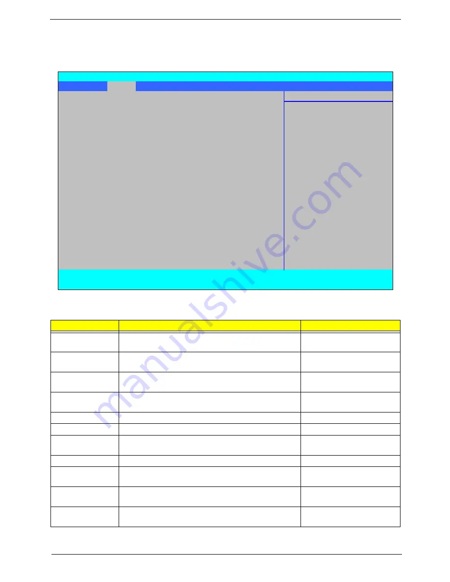
The Main screen allows the user to set the system time and date as well as enable and disable boot option
and recovery.
NOTE:
The screen above is for your reference only. Actual values may differ.
Settings in
boldface
are the default and suggested parameter settings.
Parameter
Description
Format/Option
System Time
Sets the system time. The hours are displayed with 24-
hour format.
Format: HH:MM:SS
(hour:minute:second)
System Date
Sets the system date.
Format MM/DD/YYYY
(month/day/year)
System Memory
This field reports the memory size of the system.
Memory size is fixed to 632 KB.
N/A
Extended Memory
Shows the Extended memory size. Extended Memory
size is fixed to 3965 MB
N/A
DVMT Pre-Allocated
Shows the DVMT Pre-Allocated memory size.
Option: 32,
64
, 128 MB
Quiet Boot
Select whether to display the logo screen during boot.
Option:
Enabled
or Disabled
Network Boot
Enables, disables the system boot from LAN (remote
server).
Option:
Enabled
or Disabled
F12 Boot Menu
Enables, disables Boot Menu during POST.
Option:
Disabled
or Enabled
D2D Recovery
Enables, disables the Acer D2D Recovery function
during POST by pressing
Alt-F10
.
Option:
Enabled
or Disabled
SATA Mode
Selection
Control the mode in which the SATA controller should
operate.
Option:
AHCI
or IDE Mode
Intel AMT
Enable or disable the Intel Active Management
Technology BIOS Extension.
Option:
Disabled
or
Enabled
Information
Main
Advanced
Intel
Security
Boot
Exit
Item Specific Help
System Time
[13:04:04]
System Date
[06/04/2008]
<Tab>, <Shift-Tab>, or
<Enter> selects field.
System Memory:
632 KB
Extended Memory:
3965 MB
DVMT Pre-Allocated:
[64 MB]
Quiet Boot:
[Enabled]
Network Boot:
[Enabled]
F12 Boot Menu:
[Disabled]
D2D Recovery:
[Enabled]
SATA Mode Selection:
[AHCI]
Intel AMT:
[Disabled]
F1
Help
↑↓
Select Item
F5/F6
Change Values
F9
Setup Defaults
ESC
Exit
←→
Select Menu
Enter
Select
X
Sub-Menu
F10
Save and Exit
Phoenix SecureCore(tm) Setup Utility
Summary of Contents for TravelMate 6493 Series
Page 6: ...VI ...
Page 10: ...X Table of Contents ...
Page 14: ...4 Chapter 1 System Block Diagram ...
Page 38: ...28 Chapter 1 ...
Page 56: ...46 Chapter 2 ...
Page 64: ...54 Chapter 3 7 Remove the 3G cover as shown ...
Page 71: ...Chapter 3 61 8 Press down on the locking catch to release the ODD cover and remove ...
Page 117: ...Chapter 3 107 5 Replace the MIC as shown and secure the cable with the adhesive strips ...
Page 166: ...156 Chapter 4 ...
Page 187: ...Chapter 6 177 ...
Page 220: ...Appendix A 210 ...
Page 226: ...216 Appendix C ...