6
Chapter 1
Closed Front View
9
TouchPad
Touch-sensitive pointing device which functions
like a computer mouse.
10
Click buttons (left,
center*, and right)
The left and right buttons function like the left
and right mouse buttons.
*The center button serves as Acer BioProtect
fingerprint reader supporting Acer FingerNav 4-
way control function (only for certain models).
11
Status indicators
Light-Emitting Diodes (LEDs) that light up to
show the status of the computer's functions and
components.
12
Speakers
Left and right speakers deliver stereo audio
output.
13
Power button
Turns the computer on and off.
14
Easy-launch
buttons
Buttons for launching frequently used programs.
15
Microphone
Internal microphone for sound recording.
No.
Icon
Item
Description
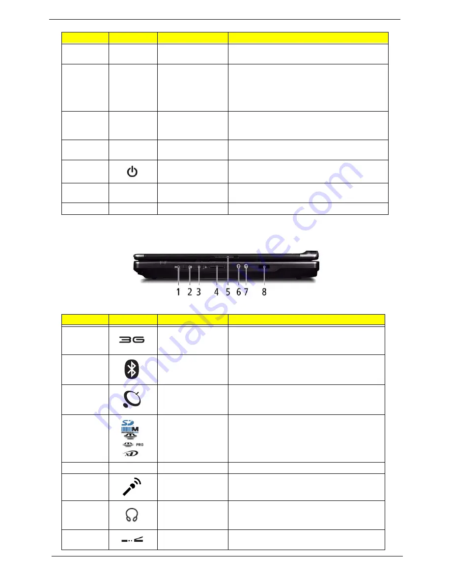
1
3G switch/indicator
Enables/disables the 3G function. Indicates the
status of 3G communication (only for certain
models).
2
Bluetooth
communication
switch/indicator
Enables/disables the Bluetooth function.
Indicates the status of Bluetooth
communication.
3
Wireless
communication
switch/indicator
Enables/disables the wireless function.
Indicates the status of wireless LAN
communication.
4
5-in-1 card reader
Accepts Secure Digital (SD), MultiMediaCard
(MMC), Memory Stick (MS), Memory Stick Pro
(MS PRO), and xDPicture Card.
Note:
Push to remove/install the card. Only
one card can operate at any given time.
5
Latch
Locks and releases the lid.
6
Microphone jack
Accepts inputs from external microphones.
7
Headphones/
speaker/line-out
jack
Connects to audio line-out devices (e.g.,
speakers, headphones).
8
Infrared port
Interfaces with infrared devices (e.g.,infrared
printer and IR-aware computer).
No.
Icon
Item
Description
Summary of Contents for TravelMate 6493 Series
Page 6: ...VI ...
Page 10: ...X Table of Contents ...
Page 14: ...4 Chapter 1 System Block Diagram ...
Page 38: ...28 Chapter 1 ...
Page 56: ...46 Chapter 2 ...
Page 64: ...54 Chapter 3 7 Remove the 3G cover as shown ...
Page 71: ...Chapter 3 61 8 Press down on the locking catch to release the ODD cover and remove ...
Page 117: ...Chapter 3 107 5 Replace the MIC as shown and secure the cable with the adhesive strips ...
Page 166: ...156 Chapter 4 ...
Page 187: ...Chapter 6 177 ...
Page 220: ...Appendix A 210 ...
Page 226: ...216 Appendix C ...