Chapter 3
59
Main Unit Disassembly Process
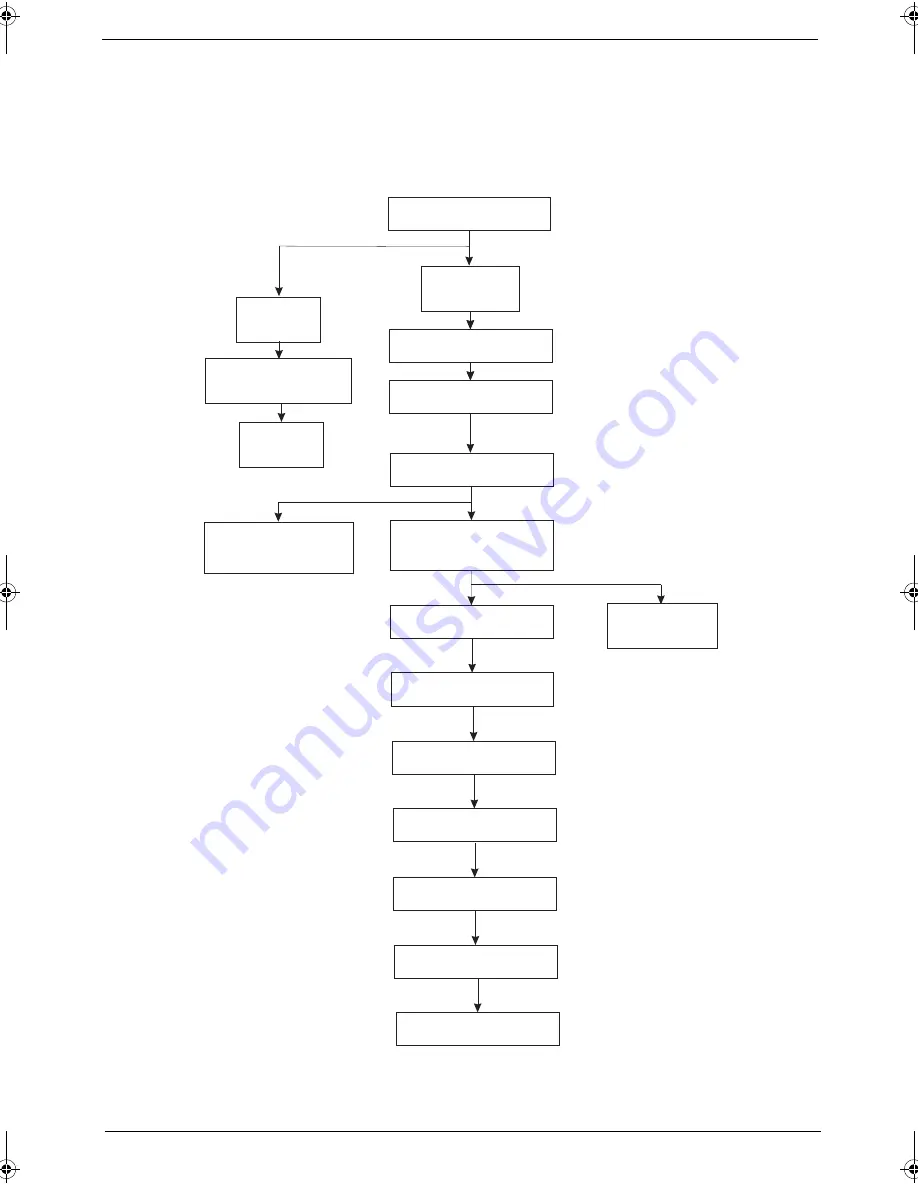
Main Unit Disassembly Flowchart
MAIN
UNIT
KEYBOARD
MAIN UNIT DISASSEMBLY
MIDDLE
COVER
LCD MODULE
Dx4
UPPER CASE
Ax1, Gx11
TOUCHPAD BRACKET
ASSEMBLY
Cx4
CPU HEATSINK
MODULE
Fx2
FAN
Hx1
FINGERPRINT
BOARD
TOUCHPAD BOARD
Ax5
CPU
Cx2
LED INDICATORS
BOARD
Cx2
Cx2
DAUGHTER BOARD
Ax1
MAIN BOARD
Cx2
MODEM BOARD
BLUETOOTH BOARD
Ax2
SPEAKER MODULES
LOWER CASE
SG_TM4720_4320_Book.book Page 59 Friday, April 20, 2007 11:14 AM
Summary of Contents for TravelMate 4720 Series
Page 10: ...x ...
Page 48: ...38 Chapter 1 ...
Page 76: ...66 Chapter 3 5 Disconnect the keyboard cable from the mainboard to remove the keyboard ...
Page 91: ...Chapter 3 81 16 Carefully detach the speaker modules as shown ...
Page 102: ...92 Chapter 3 ...
Page 120: ...110 Chapter 4 ...
Page 121: ...Chapter 5 111 System Block Diagram System Block Diagram and Connector Locations Chapter 5 ...
Page 122: ...112 Chapter 5 Board Layout Top and Bottom View ...
Page 126: ...116 Chapter 5 ...
Page 128: ...118 Chapter 4 Travelmate 4720 4320 Exploded Diagram ...
Page 141: ...131 Appendix A ...
Page 142: ...Appendix A 132 ...
Page 146: ...136 Appendix C ...


