background image

  85 

Installing Add-on Cards 

The slots on this motherboard are designed to hold expansion cards and connect them to the system bus. 
Expansion slots are a means of adding or enhancing the motherboard

s features and capabilities. With these   

efficient facilities, you can    increase the motherboard

s capabilities by adding hardware that performs tasks 

that are not part of the basic system. 


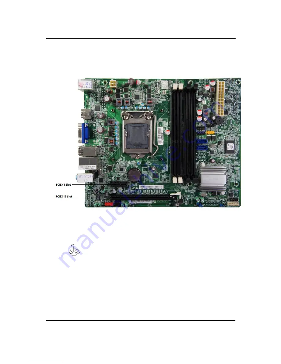
PCIE16X Slot


The PCI Express x16 slot is used to install an external PCI Express graphics card   

                                  that is fully compliant to the PCI Express Base Specification revision 2.0


PCIE1X1 Slot   


The PCI Express x1 slot is fully compliant to the PCI Express Base Specification 

  revision 2.0 as well. 


        Before installing an add-on card, check the documentation for the card carefully. If the card 
is    not Plug and Play, you may have to manually configure the card before installation. 


Summary of Contents for imedia S3811

Page 1: ...I imedia S3811 Service Guide PRINTED IN TAIWAN ...

Page 2: ...II Revision History Please refer to the table below for the updates made on imedia S3811 series guide Date Chapter Updated ...

Page 3: ...uide is subject to change without notice Acer Incorporated makes no representations or warranties either expressed or implied with respect to the contents hereof and specifically disclaims any warranties of merchantability or fitness for any particular purpose Any Acer Incorporated software described in this manual is sold or licensed as is Should the programs prove defective following their purch...

Page 4: ... bits and pieces of additional information related to the current topic WARNING Alerts your to any damage that might result from doing or not doing specific actions CAUTION Gives precautionary measures to avoid possible hardware or software problem IMPORTANT Reminds you to do specific actions relevant to the accomplishment of procedures ...

Page 5: ... NOT be covered in this generic service guide In such cases please contact your regional offices or the responsible personnel channel to provide you with further technical details 2 Please note WHEN ORDERING FRU PARTS that you should check the most up to date information available on your regional web or channel If for whatever reason a part number change is made it will not be noted in the printe...

Page 6: ...ures 26 Integrated Peripherals 27 Power Management Setup 28 PC Health Status 30 Frequency Voltage Control 31 BIOS Security Features 32 Machine Disassembly and Replacement 34 General Information 35 Standard Assembly Process 36 Standard Disassembly Process 50 Machine Disassembly and Replacement 63 Power On Self Test POST 64 POST Error Messages List 68 Error Symptoms List 70 Undetermined Problems 74 ...

Page 7: ...1333 1066 SDRAM Two PCI are supported fully compliant with PCI rev 2 2 specification at 33MHz High resolution graphics via PCI Express x16 slot intended for Graphics Interface is fully compliant to the PCI Express Base Specification revision 2 0 In addition one PCI Express slot is supported It implements an EHCI Enhanced Host Controller Interface compliant interface that provides fourteen USB 2 0 ...

Page 8: ... Express slot l Integrated two SATA 3 0 Gb s Host Controller l Fourteen USB 2 0 ports supported l Serial Peripheral Interface SPI support l Integrated Graphics Support with PAVP 1 5 l Intel High Definition Audio Controller Memory l Supports DDR3 1333 1066 DDR3 SDRAM with Dual channel architecture l Accommodates four unbuffered DIMMs l Up to 4 GB per DIMM with maximum memory size up to 16 GB Onboar...

Page 9: ...gure many system features including the following l Power management l Wake up alarms l CPU parameters l CPU and memory timing l Graphic parameters The firmware can also be used to set parameters for different processor clock speeds 1 Some hardware specifications and software items are subject to change without prior notice 2 Due to chipset limitation we recommend that motherboard be operated in t...

Page 10: ...Standard 24 pin ATX power connector 7 USB1 2 4 Front panel USB headers 8 USB 3 Front panel CR headers 9 SATA1 2 Serial ATA connectors 10 GPIO1 2 GPIO header 1 2 11 BIOS_FLASH Reflash BIOS connectors 12 F_PANEL Front panel switch LED header 13 BIOS_WP BIOS Write protection connectors 14 CLR_CMOS Clear CMOS jumper 15 ME_Enable ME Enable Disable header 16 SPDIF_OUT SPDIF out header 17 SPK Internal sp...

Page 11: ...5 Block Diagram ...

Page 12: ...xternal microphones 2 Headphone Speaker out line out port Connects to audio line in devices e g speakers headphones 3 SD SDHC MMC SD Plus Ultra II SD PLUS Memory Card SDHC Secure Digital High Capacity MMC Plus MultiMediaCard PLUS 4 xD MS MS Pro XD MS Memory Stick MS Pro Memory Stick PRO 5 USB ports Connects to USB 2 0 devices e g USB mouse USB camera ...

Page 13: ...onnects to USB 2 0 devices e g USB mouse USB camera 4 Microphone jack Accepts input from external microphones 5 Line out jack Accepts audio line in devices e g audio CD player 6 PS 2 mouse connector 7 Network port Lights to indicate the status of wireless LAN communications 8 Line in jack Accepts audio line out devices e g audio CD player ...

Page 14: ... Audio Jack Function Table Color Use Headphone 2CH 4CH 5 1CH Blue Line in Line in Rear Speaker Rear Speaker Green Headphone Front speaker Front speaker Front speaker Pink Mic in Mic in Mic in Center bass ...

Page 15: ... Use the USB ports to connect USB devices 4 LAN Port Connect an RJ 45 jack to the LAN port to connect your computer to the Network 5 Line in Line out Microphone Use the three audio ports to connect audio devices The first jack is for stereo line in signal The second jack is for stereo line out signal The third jack is for microphone 6 PS2Keyboard Use the lower PS 2 port to connect a PS 2 keyboard ...

Page 16: ...the PS 2 mouse port or USB port on the back panel of the system Keyboard PS 2 or USB manufacturing option Connect the keyboard to the PS 2 keyboard port or USB port on the back panel of the system Speakers For systems bundled with speakers before powering on the system connect the speaker cable to the audio out external speaker port on the back panel of the system For more detailed information abo...

Page 17: ...ed computers include an all in one memory card reader that allows you read and write the most common types such as SD Secure Digital MMC Multi Media Card CF Compact Flash xD XD PICTURE CARD Micro SD and MS MS Pro Memory Stick NOTE Card reader are optional and the appearance might be different depending on the actual product ...

Page 18: ...pport protocol ACPI 2 0 APM 1 2 SMBIOS 2 3 WFM support ASD Boot from CD ROM feature Yes Support to LS 120 FDD drive Yes NOTE The BIOS can be overwritten upgraded by using the flash utility BIOS Hotkey List Item Specification Specification DEL Enter BIOS Setup Utility Press while the system is booting to enter BIOS setup Utility F12 Enter Boot Menu Press while the system is booting to enter Boot Me...

Page 19: ... same memory size DDRII memory module Cache Memory Item Specification First Level Cache Configurations Cache function control Always enabled Second Level Cache Configurations L2 Cache RAM size Up to 2MB per core exclusive L2 Cache RAM speed One half the processor core clock frequency L2 Cache function control Enable Disable by BIOS Setup Video Interface Item Specification Video controller Intel H5...

Page 20: ... Class Support legacy keyboard for legacy mode USB Number support up to 12 ports Power Management Devices S1 Idle S3 Suspend to RAM S4 Suspend to DIsk S5 Shut Down Power Button Enabled Enabled Enabled Disabled USB Keyboard Enabled Enabled Enabled N A LAN Disabled Disabled Disabled Disabled RTC Disabled Enabled Disabled Disabled Modem Ring Disabled Disabled Disabled N A ...

Page 21: ... button modem ring in keyboard and mouse for APM mode l Resume recovery time 7 10 sec Suspend Mode l Independent power management timer 2 120 minutes time step 10 minutes or pushing external l switch button l CPU goes into SMM l CPU asserts STPCLK and goes into the Stop Grant State l LED on the panel turns amber colour l Hard disk drive goes into SLEEP mode for ATA standard interface l Disable H s...

Page 22: ...gs made in the Setup Utility affect how the computer performs Before using the Setup Utility ensure that you understand the Setup Utility options This chapter provides explanations for Setup Utility options The Standard Configuration A standard configuration has already been set in the Setup Utility However we recommend that you read this chapter in case you need to make any changes in the future ...

Page 23: ...hout Saving Move Enter Select Value F10 Save Exit Setup Esc Exit F1 General Help F9 Load Default Settings V02 66 Copyright 1985 2010 American Megatrends Inc The default BIOS setting for this motherboard applies for most conditions with optimum performance It is not suggested to change the default values in the BIOS setup and the manufacture takes no responsibility to any damage caused by changing ...

Page 24: ... 6 At the A prompt type the Flash Utility program name and press Enter 7 Type the filename of the new BIOS in the File Name to Program text box Follow the onscreen directions to update the motherboard BIOS 8 When the installation is complete remove the floppy diskette from the diskette drive and restart your computer If your motherboard has a Flash BIOS jumper reset the jumper to protect the newly...

Page 25: ...n P01 A4 BIOS Release Date 08 19 2010 Asset Tag Number Move Enter Select Value F10 Save Exit Setup Esc Exit F1 General Help F9 Load Default Settings Press ESC to return to the main menu setting page For the purpose of better product maintenance the manufacture reserves the right to change the BIOS items presented in this manual The BIOS setup screens shown in this chapter are for reference only an...

Page 26: ...DROM Use ENTER TAB or SHIFT TAB to select a field Halt On All But Keyboard Use or to configure system Date Move Enter Select Value F10 Save Exit Setup Esc Exit F1 General Help F9 Load Default Settings Date and Time The Date and Time items show the current date and time on the computer If you are running a Windows OS these items are automatically updated whenever you make changes to the Windows Dat...

Page 27: ...xit Setup Esc Exit F1 General Help F9 Load Default Settings SATA Port0 Auto Use this item to configure the type of the IDE device that you specify If the feature is enabled it will enhance hard disk performance by reading or writing more data during each transfer S M A R T Enabled The S M A R T Self Monitoring Analysis and Reporting Technology system is a diagnostics technology that monitors and p...

Page 28: ... Press Enter Bootup Num Lock On USB Beep Message Disabled Move Enter Select Value F10 Save Exit Setup Esc Exit F1 General Help F9 Load Default Settings Quick Boot Enabled If you enable this item the system starts up more quickly be elimination some of the power on test routines Quiet Boot Enabled This item is used to enable disable the quiet boot Disabled Displays the normal POST messages Enabled ...

Page 29: ... Help F9 Load Default Settings uOptical Disk Drive Priority D DVD Drives Press Enter Scroll to this item and press Enter to view the following screen CMOS Setup Utility Optical Disk Drive Priority Item Help Optical Disk Drive Priority Specifies the boot 1st Drive ATAPI DVD A DH16A6S sequence from the available devices Move Enter Select Value F10 Save Exit Setup Esc Exit F1 General Help F9 Load Def...

Page 30: ...ility Removable Device Priority Item Help Removable Device Specifies the boot 1st Drive USB Generic Compact sequence from the 2nd Drive USB Multiple Flash available devices Move Enter Select Value F10 Save Exit Setup Esc Exit F1 General Help F9 Load Default Settings Press Esc to return to the Advanced BIOS Features screen ...

Page 31: ...the available devices Move Enter Select Value F10 Save Exit Setup Esc Exit F1 General Help F9 Load Default Settings Boot Up NumLock On This item defines if the keyboard Num Lock key is active when your system is started USB Beep Message Disabled This item disables enables the beep during USB device enumeration Press Esc to return to the Advanced BIOS Features screen Press Esc to return to the main...

Page 32: ...tomatically adjusts Intel processor Voltage and core Frequency according To system performance Demand Move Enter Select Value F10 Save Exit Setup Esc Exit F1 General Help F9 Load Default Settings Intel EIST Enabled This item allows users to enable or disable the EIST Enhanced Intel SpeedStep technology Intel Turbo Boost Enabled This item enables or disables Intel Turbo Boost Intel XD Bit Enabled T...

Page 33: ...r OnBoard USB Controller Enabled Use this item to enable or disable the use of USB controller Legacy USB Support Enabled Use this item to enable or disable support for legacy USB devices Setting to Auto allows the system to detect the presence of USB device at startup If detected the USB controller legacy mode is enabled If no USB device is detected the legacy USB support is disabled USB Storage E...

Page 34: ...you install a software power down that is controlled by the power button on your system If the item is set to Instant Off then the power button causes a software power down If the item is set to Delay 4 Sec then you have to hold the power button down for four seconds to cause a software power down Power On by RTC Alarm Disabled The system can be turned off with a software command If you enable thi...

Page 35: ... State This item defines how the system will act after AC power loss during system operation When you set to Off it will keep the system in Off state until the power button is pressed Press Esc to return to the main menu setting page ...

Page 36: ...tem Temperature 41 C 105 F CPU Fan Speed 1104 RPM System Fan Speed N A CPU Core 1 152 V 1 05V 1 392 V 3 30V 3 024 V 5 00V 5 068 V 12 0V 11 831 V 5VSB 4 945 V VBAT 3 336 V Smart Fan Enabled Move Enter Select Value F10 Save Exit Setup Esc Exit F1 General Help F9 Load Default Settings SMART Fan Enabled This item allows you to enable disable the control of the system fan speed by changing the fan volt...

Page 37: ...All DIMM PCI PCIE Enabled Spread Spectrum Enabled Options Disabled Enabled Move Enter Select Value F10 Save Exit Setup Esc Exit F1 General Help F9 Load Default Settings Clock to All DIMM PCI PCIE Emabled This item allows you to enable or disable the Clock to all DIMM PCIE Spread Spectrum Enabled If you enable spread spertrum it can significantly reduce the EMI Electro Magneticinterface generated b...

Page 38: ...s been set If the password has been installed Installed displays If not Not Installed displays User Password Not Installed This item indicates whether a user password has been set If the password has been installed Installed displays If not Not Installed displays Change Supervisor Password Press Enter You can select this option and press Enter to access the sub menu You can use the sub menu to cha...

Page 39: ...urn to the main menu Exit Without Saving Highlight this item and press Enter to discard any changes that you have made in the Setup Utility and exit the Setup Utility When the Exit Without Saving dialog box appears select OK to discard changes and exit or select Cancel to return to the main menu If you have made settings that you do not want to save use the Exit Without Saving item and select OK t...

Page 40: ...nd conductive mat for preventing electrostatic discharge l Wire cutter l Phillips screwdriver may require different size NOTE The screws for the different components vary in size During the disassembly process group the screws with the corresponding components to avoid mismatches when putting back the components Chapter3 ...

Page 41: ...fore You Begin Before proceeding with the disassembly procedure make sure that you do the following 1 Turn off the power to the system and all peripherals 2 Unplug the AC adapter and all power and signal cables from the system ...

Page 42: ...36 Standard Assembly Process 1 Opening the chassis 1 1 Remove the two screws 1 2 Remove side cover 2 Removing PSU bracket 2 1 Rotate the PSU bracket ...

Page 43: ...37 3 Removing HDD bracket 3 1 Remove the screw 3 2 Rotate the bracket 4 Removing front bezel 4 1 Pushing three hooks ...

Page 44: ...38 4 2 Rotate the front bezel 5 Insert the ODD devices 5 1 Pushing HDD devices into bracket 5 2 Fix two screws ...

Page 45: ...39 6 Setting the Motherboard 6 1 Motherboard view 6 2 Open the CPU cover 6 3 Put the CPU in the seat and close the cover ...

Page 46: ...40 6 4 Tie CPU fan cable 6 5 Pulling in CPU fan power cable to MB 6 6 Fix four screws of CPU Cooler connect to MB ...

Page 47: ...atch 6 8 Press down the memory 6 9 Memory install rule 1 DIMM4 DIMM2 DIMM3 DIMM1 1x1G 1GB 2x1G 1GB 1GB 3x1G 1GB 1GB 1GB 4x1G 1GB 1GB 1GB 1GB 1x1G 1x2G 1GB 2GB 1x2G 2GB 2x2G 2GB 2GB 3x2G 2GB 2GB 2GB 4x2G 2GB 2GB 2GB 2GB 1 3 2 4 ...

Page 48: ...42 7 Assembly motherboard 7 1 Pushing rear I O Shield in chassis 7 2 Insert the motherboard and fix six screws 8 Insert the system Fan 8 1 Tie system fan cable ...

Page 49: ...43 8 2 Pushing system fan 8 3 Fix two screw 8 4 Pulling in system fan power cable to MB ...

Page 50: ...44 9 Pulling in Audio USB1 CR PANEL cable to MB and put in cable clip 10 Insert the HDD 10 1 Pushing HDD into bracket 10 2 Fix four screws Front Back ...

Page 51: ...45 10 3 Pushing HDD into chassis 10 4 Fix the screws 11 Pulling in HDD ODD SATA cable on Motherboard SATA 1 HDD SATA 2 ODD SATA 1 SATA 2 ...

Page 52: ...46 12 Insert VGA card 12 1 Rotate the bracket 12 2 Remove PCI slot 12 3 Install VGA card on motherboard ...

Page 53: ...47 12 4 Rotate the bracket 13 Insert the PSU 13 1 Pushing PSU into bracket 13 2 Fix four screws 13 3 ATV 12V power cable insert ...

Page 54: ...48 13 4 ATX power cable insert 13 5 Insert the ODD HDD power cable Insert the ODD power cable Insert the HDD power cable Long for HDD used Short for ODD used ...

Page 55: ...49 14 Overview ...

Page 56: ...50 Standard Disassembly Process 1 Opening the chassis 1 1 Remove the two screws 1 2 Remove the side cover 2 Removing the power supply 2 1 Rotate the power supply ...

Page 57: ...51 2 2 Pulling out the 20 pins power connector and 4 pins power connector 2 3 Pulling out the ODD power cable and HDD power cable 2 4 Remove four screws ...

Page 58: ...52 2 5 Remove the power supply 3 Pulling out the SATA ODD cable and SATA HDD cable 4 Removing the HDD 4 1 Remove the screw ODD Cable HDD Cable ...

Page 59: ...53 4 2 Rotate the bracket 4 3 Remove four screws 4 4 Remove the HDD Front Back ...

Page 60: ...54 5 Removing the VGA Card 5 1 Rotate the bracket 5 2 Remove the VGA Card 6 Pulling out the Audio USB1 CR PANEL cable ...

Page 61: ...55 7 Removing system Fan 7 1 Pulling out the system Fan cable 7 2 Remove two screws 7 3 Remove system Fan ...

Page 62: ...e RTC battery NOTE Circuit boards 10 cm has been highlighted with the yellow rectangle as above image shows Please detach the Circuit boards and follow local regulations for disposal NOTE RTC battery has been highlighted with the yellow circle as above image shows Please detach the RTC battery and follow local regulations for disposal ...

Page 63: ...57 8 4 Pulling out the CPU cooler power cable from the main board 8 5 Remove the four CPU Cooler screws 8 6 Remove the CPU ...

Page 64: ...58 8 7 Release the four latch show bellow then remove the Memory 9 Removing front bezel 9 1 Pushing three hooks 9 2 Rotate the front bezel ...

Page 65: ...59 10 Removing the ODD 10 1 remove two screws 10 2 Pulling out the ODD 11 Removing the ODD bracket 11 1 Remove five screws ...

Page 66: ...60 11 2 Removing the ODD bracket 12 Pulling out Card reader USB Audio module and power switch HDD led cable 12 1 Removing top bezel Pushing the hooks 12 2 Removing Cable Tie ...

Page 67: ...61 12 3 Pushing the Cable 12 4 Removing power switch HDD LED _holder 12 5 Pulling out HDD LED cable Front Back ...

Page 68: ...62 12 6 Removing power switch HDD led cable 12 7 Removing HDD led housing 12 8 Removing the two screw and pulling out Card reader USB Audio module ...

Page 69: ...ssembly and Replacement This chapter provides troubleshooting information for the imedia S3811 Service Guide l Power On Self Test POST l POST Error Messages List l Error Symptoms List l Undetermined Problems Chapter4 ...

Page 70: ...mpatible keyboard port NOTE When Post executes a task it uses a series of preset numbers called check points to be latched at port 80h indicating the stages it is currently running This latch can be read and shown on a debug board The following table describes the BIOS common tasks carried out by POST Each task is denoted by an unique check point number For other unique check point numbers that ar...

Page 71: ... gets control for IRQ1 Uncompress all available language BIOS logo and Silent logo modules 13 Early POST initialization of chipset registers 20 Relocate System Management Interrupt vector for all CPU in the system 24 Uncompress and initialize any platform specific BIOS modules GPNV is 2A Initializes different devices through DIM 2C Initializes different devices Detects and initializes the video ad...

Page 72: ...n that needs an adjustment in system RAM size if needed 60 Initializes NUM LOCK status and programs the KBD typematic rate 75 Initialize Int 13 and prepare for IPL detection 78 Initializes IPL devices controlled by BIOS and option ROMs 7C Generate and write contents of ESCD in NVRam 84 Log errors encountered during POST 85 Display errors to the user and gets the user response for error 87 Execute ...

Page 73: ...lay boot option popup menu A7 Displays the system configuration screen if enabled Initialize the CPU s before boot which includes the programming of the MTRR s A9 Wait for user input at config display if needed AA Uninstall POST INT1Ch vector and INT09h vector AB Prepare BBS for Int 19 boot Init MP tables AC End of POST initialization of chipset registers De initializes the ADM module B1 Save syst...

Page 74: ...ating the BIOS code may have become corrupt Contact your system dealer to replace the BIOS CMOS Battery Failed The CMOS battery is no longer functional Contact your system dealer for a replacement the BIOS CMOS Checksum Error defaults loaded Checksum of CMOS is incorrect so the system loads the default equipment configuration A checksum error may indicate that CMOS has become corrupt A weak batter...

Page 75: ...ars giving specifics about the type and location of the memory error Override enabled Defaults loaded If the system cannot boot using the current CMOS configuration the BIOS can override the current configuration with a set of BIOS defaults designed for the most stable minimal performance system operations Press TAB to show POST screen System OEMs may replace the Phoenix Technologies Award BIOS PO...

Page 76: ...repeated during POST 1 Insert the memory modules in the DIMM sockets properly then reboot the system 2 Memory module 3 Main board System works but fails to enter power saving mode when the Power Management Mode is set to Enabled 1 Enter BIOS Setup and load default settings In Windows Systems check settings in Power Management Property of Control Panel 2 Reload software from Recovery CD Blinking cu...

Page 77: ...ive CD DVD ROM drive can play audio CD but no sound output 1 Ensure the headphone jack of the CD DVD ROM has an output 2 Turn up the sound volume 3 Speaker power connection cable 4 CD DVD ROM drive Real Time Clock Real time clock is inaccurate 1 Ensure the information in the Standard CMOS Feature of BIOS Setup is set correctly 2 RTC battery 3 Main board Audio Audio software program invokes but no ...

Page 78: ...ports presence before diagnosing any parallel serial ports problems Serial or parallel port loop back test failed 1 Make sure that the LPT or COM you test is the same as the setting in BIOS Setup 2 Loop back 3 Main board Printing failed 1 Ensure the printer driver is properly installed Refer to the printer service manual 2 Printer 3 Printer cable 4 Main board Printer problems 1 Refer to the servic...

Page 79: ...enu does not turn off the system Only pressing power switch can turn off the system 1 Load default settings 2 Reload software from Recovery CD No system power or power supply fan is not running 1 Power Supply 2 Main board Other Problems Any other problems 1 Undetermined Problems ...

Page 80: ...ve isolated the problem FRU 4 Load default settings in setup 5 Check all main board jumper positions and switch settings 6 Check all adapter card jumper positions 7 Check all device jumper positions 8 Check all cables and connectors for proper installation 9 If the jumpers switches and voltage settings are correct remove or disconnect the following one at a time 10 Non Acer devices l External devi...

Page 81: ...pports all the features required Secondly this motherboard supports one or two floppy diskette drives and two enhanced IDE drives Make sure that your case has sufficient power and space for all drives that you intend to install Most cases have a choice of I O templates in the rear panel Make sure that the I O template in the case matches the I O ports installed on the rear edge of the motherboard ...

Page 82: ...to set system configuration options Jumpers with more than one pin are numbered When setting the jumpers ensure that the jumper caps are placed on the correct pins The illustrations show a 2 pin jumper When the jumper cap is placed on both pins the jumper is SHORT If you remove the jumper cap or place the jumper cap on just one pin the jumper is OPEN SHORT OPEN This illustration shows a 3 pin jump...

Page 83: ... motherboard jumpers Pin 1 is labeled Jumper Settings Jumper Type Description Setting Default IIIustration CLR_CMOS 3 pin CLEAR CMOS 1 2 NORMAL 2 3 CLEAR Before clearing the CMOS make sure to turn the system off 1 CLR_COMS ME_ENABLE 3 pin MEENABLE 1 2 NORMAL 2 3 CLEAR 1 ME_DISABLE ...

Page 84: ...tor to ATX_POWER 3 Connect the auxiliary case power supply connector to ATX12V 4 Connect the case switches and indicator LEDs to the F_PANEL 5 Connect the system cooling fan connector to SYS_FAN 6 Connect the case speaker cable to SPK Connecting 24 pin power cable Users please note that when installing 24 pin power cable the latche of power cable falls on the left side of the ATX_POWER1connector l...

Page 85: ...Sensor ATX_POWER ATX 24 pin Power Connector Pin Signal Name Pin Signal Name 1 3 3V 13 3 3V 2 3 3V 14 12V 3 Ground 15 COM 4 5V 16 PS_ON 5 Ground 17 Ground 6 5V 18 Ground 7 Ground 19 Ground 8 PWRGD 20 5V 9 5VSB 21 5V 10 12V 22 5V 11 12V 23 5V 12 3 3V 24 Ground ATX12V ATX 12V Power Connector Pin Signal Name 1 Ground 2 Ground 3 12V 4 12V SPK Internal speaker Pin Signal Name Pin Signal Name 1 Output 2 ...

Page 86: ...nboard IDE interface The LED will also show activity for devices connected to the SCSI hard drive activity LED connector Power Sleep Message waiting LED Connecting pins 2 and 4 to a single or dual color front panel mounted LED provides power on off sleep and message waiting indication Reset Switch Supporting the reset function requires connecting pin 5 and 7 to a momentary contact switch that is n...

Page 87: ... Processor This motherboard automatically determines the CPU clock frequency and system bus frequency for the processor You may be able to change these settings by making changes to jumpers on the motherboard or changing the settings in the system Setup Utility We strongly recommend that you do not over clock processors or other components to run faster than their rated speed Warning Over clocking...

Page 88: ...he Load Plate Rotate the load plate onto the package IHS Intergraded Heat Spreader Engage the load lever while pressing down lightly onto the load plate Secure the load lever with the hook under retention tab F Fasten the cooling fan supporting base onto the CPU socket on the motherboard G Make sure the CPU fan is plugged to the CPU fan connector Please refer to the CPU cooling fan user s manual f...

Page 89: ...when you handle the modules Installation Procedure Refer to the following to install the memory modules 1 This motherboard supports unbuffered DDR3 SDRAM only 2 Push the latches on each side of the DIMM slot down 3 Align the memory module with the slot The DIMM slots are keyed with notches and the DIMMs are keyed with cutouts so that they can only be installed correctly 4 Check that the cutouts on...

Page 90: ... to the SATA hard drive or the connector on the motherboard SATA cable optional SATA power cable optional Refer to the illustration below for proper installation 1 Attach either cable end to the connector on the motherboard 2 Attach the other cable end to the SATA hard drive 3 Attach the SATA power cable to the SATA hard drive and connect the other end to the power supply This motherboard does not...

Page 91: ...re that performs tasks that are not part of the basic system PCIE16X Slot The PCI Express x16 slot is used to install an external PCI Express graphics card that is fully compliant to the PCI Express Base Specification revision 2 0 PCIE1X1 Slot The PCI Express x1 slot is fully compliant to the PCI Express Base Specification revision 2 0 as well Before installing an add on card check the documentati...

Page 92: ...d on card into the expansion slot Ensure that the edge connector is correctly seated in the slot 3 Secure the metal bracket of the card to the system case with a screw 1 For some add on cards for example graphics adapters and network adapters you have to install drivers and software before you can begin using the add on card 2 The onboard PCI interface does not support 64 bit SCSI cards ...

Page 93: ...o header This header allows the user to install auxiliary front oriented microphone and line out ports for easier access Pin Signal Name Pin Signal Name 1 PORT 1L 2 AUD_GND 3 PORT 1R 4 PRESENCE 5 PORT 2R 6 SENSE1_RETURN 7 SENSE_SEND 8 KEY 9 PORT 2L 10 SENSE2_RETURN GPIO1 2 Button recovery jumper Pin Signal Name Pin Signal Name 1 GP36 GP16 2 GND ...

Page 94: ...ion 1 5VA 5V analog Power 2 Key No pin 3 SPDIF SPDIF digital output 4 GND Ground F_USB1 4 Front Panel USB headers The motherboard has four USB ports installed on the rear edge I O port array Additionally some computer cases have USB ports at the front of the case If you have this kind of case use auxiliary USB connector to connect the front mounted ports to the motherboard Pin Signal Name Function...

Page 95: ...LA_HEAD 7 SM_PCI_EMI_SHIELDING 28 TOP COVER CABLE ROUTING 8 SM_PCI_CLAMP 29 TOP COVER 9 SM_REAR_PLATE 30 TOP MAIN_BEZEL 10 SM_POWER_ASM_BKT 31 SPRING_ODD_EJECTION 11 SM_MB_BKT 32 POWER BUTTOM 12 STANDOFF 33 MYLAR 13 CLIP 34 HDD LENS 14 STANDOFF_FIX 35 EJECT_CONNECT 15 SCREW FOR ODD_CAGE 36 EJECT BOTTOM 16 SM_C_BASE 37 FRONT MAIN_BEZEL W_CR 17 CHASSIS FOOT 38 ODD DOOR 18 SM_DUST_COVER 39 SPRING_DOO...

Page 96: ...90 ...

Page 97: ...SM_PCI_EMI_SHIELDING 28 TOP COVER CABLE ROUTING 8 SM_PCI_CLAMP 29 TOP COVER 9 SM_REAR_PLATE 30 TOP MAIN_BEZEL 10 SM_POWER_ASM_BKT 31 SPRING_ODD_EJECTION 11 SM_MB_BKT 32 POWER BUTTOM 12 STANDOFF 33 MYLAR 13 CLIP 34 HDD LENS 14 STANDOFF_FIX 35 EJECT_CONNECT 15 SCREW FOR ODD_CAGE 36 EJECT BOTTOM 16 SM_C_BASE 37 FRONT MAIN_BEZEL W_CR 17 CHASSIS FOOT 38 ODD DOOR 18 SM_DUST_COVER 39 SPRING_DOOR_ODD 19 L...

Page 98: ...92 ...

Page 99: ...93 FRU List The FRU list will be updated later ...

Reviews: