68
Chapter 4
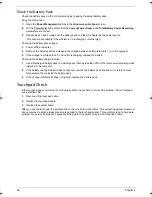
Check the Battery Pack
Check the battery pack via the OS control and by checking the actual battery pack.
Using the OS control:
1.
Open the
Power Management
setting in the Windows Control Panel screen.
2.
On the Power Meter tab, confirm that the
Current Power Source
and
Total Battery Power Remaining
parameters are correct.
3.
Repeat steps 1 and 2 using both the battery pack and the AC adapter as the power source.
This will help you identify if the problem is on recharging or discharging.
Checking the battery pack voltage:
1.
Power off the computer.
2.
Remove the battery pack and measure the voltage between battery terminals 1 (+) and 6 (ground).
3.
If the voltage is still less than 7.5 Vdc after recharging, replace the battery.
Checking the battery charge function:
1.
Use a discharged battery pack or a battery pack that has less than 50% of the total power remaining when
installed in the computer.
2.
If the battery charge indicator does not light up, remove the battery pack and allow it to return to room
temperature, then reinstall the battery pack.
3.
If the charge indicator still does not light up, replace the battery pack.
Touchpad Check
If the touchpad doesn’t work, do the following actions one at a time to correct the problem. Do not replace a
non-defective FRU:
1.
Reconnect the touchpad cable.
2.
Replace the touchpad board.
3.
Replace the system board.
After you use the touchpad, the pointer drifts on the screen for a short time. This self-acting pointer movement
can occur when a slight, steady pressure is applied to the touchpad pointer. This symptom is not a hardware
problem. No service actions are necessary if the pointer movement stops in a short period of time.
Acer TM 4520 SG.book Page 68 Friday, June 22, 2007 5:43 PM
Summary of Contents for Extensa 4120
Page 6: ...VI ...
Page 10: ...X Table of Contents ...
Page 36: ...26 Chapter 2 ...
Page 93: ...Chapter 5 83 System Block Diagram System Block Diagram and Board Layout Chapter 5 ...
Page 98: ...88 Chapter 6 Aspire 5910 Exploded Diagram ...
Page 100: ...90 Chapter 6 Cables Category No Part Name and Description Acer Part No ...
Page 101: ...Chapter 6 91 Fan Hard Disk Drive Category No Part Name and Description Acer Part No ...
Page 102: ...92 Chapter 6 Keyboard Category No Part Name and Description Acer Part No ...
Page 103: ...Chapter 6 93 Keyboard TM LCD Panel Category No Part Name and Description Acer Part No ...
Page 104: ...94 Chapter 6 Mechanical parts Category No Part Name and Description Acer Part No ...
Page 105: ...Chapter 6 95 Memory Optical Disc Drive Category No Part Name and Description Acer Part No ...
Page 106: ...96 Chapter 6 Power related Processor Category No Part Name and Description Acer Part No ...
Page 107: ...Chapter 6 97 Screws Miscellaneous Category No Part Name and Description Acer Part No ...
Page 108: ...98 Chapter 6 Category No Part Name and Description Acer Part No Audio related Boards ...
Page 109: ...Chapter 6 99 Cables Category No Part Name and Description Acer Part No ...
Page 110: ...100 Chapter 6 Fan Hard Disk Drive Category No Part Name and Description Acer Part No ...
Page 111: ...Chapter 6 101 Keyboard Category No Part Name and Description Acer Part No ...
Page 112: ...102 Chapter 6 Keyboard TM LCD Panel Category No Part Name and Description Acer Part No ...
Page 113: ...Chapter 6 103 Mechanical parts Category No Part Name and Description Acer Part No ...
Page 114: ...104 Chapter 6 Memory Optical Disc Drive Category No Part Name and Description Acer Part No ...
Page 115: ...Chapter 6 105 Power related Processor Category No Part Name and Description Acer Part No ...
Page 116: ...106 Chapter 6 Screws Miscellaneous Category No Part Name and Description Acer Part No ...
Page 122: ...112 Appendix A ...
Page 136: ...126 Appendix C ...
Page 143: ...Index 133 ...


