Chapter 3
55
Removing the LCD Module
1.
See “Removing the Keyboard” on page 54.
2.
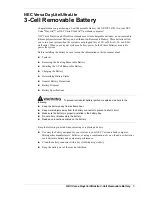
Turn the computer over. Remove the two securing screws from the bottom of the chassis.
3.
Remove the Antenna Cables from the cable channel as shown. Ensure that the cables are free from all cable
clips.
Step
Size
Quantity
Screw Type
LCD Module
M2.5*8
2
Summary of Contents for eMachines E630 Series
Page 6: ...VI...
Page 10: ...X Table of Contents...
Page 14: ...4 Chapter 1 System Block Diagram...
Page 70: ...60 Chapter 3 4 Disconnect the following four cables from the Mainboard A B C D...
Page 83: ...Chapter 3 73 4 Using both hands lift the Thermal Module clear of the Mainboard...
Page 85: ...Chapter 3 75 4 Lift the CPU Fan clear of the Mainboard as shown...
Page 91: ...Chapter 3 81 5 Lift the LCD Panel clear of the module...
Page 99: ...Chapter 3 89 9 The Antennas and cables appear as shown when correctly installed...
Page 104: ...94 Chapter 3 2 Replace the four screws and screw caps provided...
Page 109: ...Chapter 3 99 5 Replace the FFC and press down as indicated to secure it to the Upper Cover...
Page 120: ...110 Chapter 3 17 Replace the two screws securing the LCD Module to the Lower Cover...
Page 128: ...118 Chapter 3...
Page 150: ...140 Chapter 4...
Page 156: ...146 Chapter 5...
Page 158: ...148 Chapter 6 E630 E430 Exploded Diagrams Main Assembly 1 2 3 4 5...
Page 171: ...Chapter 6 161...
Page 192: ...182 Appendix B...
Page 194: ...184 Appendix C...
Page 198: ...188...