


144
Chapter 5
Clearing Password Check and BIOS Recovery
This section provides you with the standard operating procedures of clearing password and BIOS recovery for
E630/E430 5517. The machine provides one Hardware Open Gap on main board for clearing password
check, and one Hotkey for enabling BIOS Recovery.
Clearing Password Check
Steps for Clearing BIOS Password Check
If users set BIOS Password (Supervisor Password and/or User Password) for a security reason, BIOS will ask
the password during systems POST or when systems enter to BIOS Setup menu. However, once it is
necessary to bypass the password check, users need to short the HW Gap to clear the password by the
following steps:
1.
Power Off the system, and remove HDD, AC and Battery from the machine.
2.
Disconnect the RTC Battery cable and locate the J1 jumper.
3.
Use an electric conductivity tool to short the two points of the HW Gap.
4.
Plug in AC, keep the short condition on the HW Gap, and press Power Button to power on the system till
BIOS POST finish. Then remove the tool from the HW Gap.
5.
Restart system. Press
F2
key to enter BIOS Setup menu.
6.
If there is no Password request, BIOS Password is cleared. Otherwise, please follow the steps and try
again.
NOTE:
These steps are only for clearing BIOS Password (Supervisor Password and User Password).
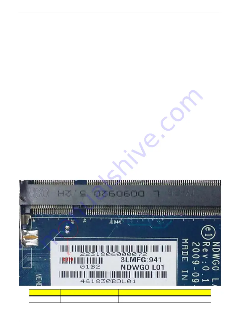
Clear CMOS Jumper
Item
Description
Location
R379
Clear CMOS Jumper
Under DIMM Cover
Summary of Contents for eMachines E630 Series
Page 6: ...VI...
Page 10: ...X Table of Contents...
Page 14: ...4 Chapter 1 System Block Diagram...
Page 70: ...60 Chapter 3 4 Disconnect the following four cables from the Mainboard A B C D...
Page 83: ...Chapter 3 73 4 Using both hands lift the Thermal Module clear of the Mainboard...
Page 85: ...Chapter 3 75 4 Lift the CPU Fan clear of the Mainboard as shown...
Page 91: ...Chapter 3 81 5 Lift the LCD Panel clear of the module...
Page 99: ...Chapter 3 89 9 The Antennas and cables appear as shown when correctly installed...
Page 104: ...94 Chapter 3 2 Replace the four screws and screw caps provided...
Page 109: ...Chapter 3 99 5 Replace the FFC and press down as indicated to secure it to the Upper Cover...
Page 120: ...110 Chapter 3 17 Replace the two screws securing the LCD Module to the Lower Cover...
Page 128: ...118 Chapter 3...
Page 150: ...140 Chapter 4...
Page 156: ...146 Chapter 5...
Page 158: ...148 Chapter 6 E630 E430 Exploded Diagrams Main Assembly 1 2 3 4 5...
Page 171: ...Chapter 6 161...
Page 192: ...182 Appendix B...
Page 194: ...184 Appendix C...
Page 198: ...188...


