


30
Chapter 2
Changing a Password
1.
Use the
↑
and
↓
keys to highlight the Set Supervisor Password parameter and press the
Enter
key. The
Set Password box appears.
2.
Type the current password in the Enter Current Password field and press
Enter
.
3.
Type a password in the Enter New Password field. Retype the password in the Confirm New Password
field.
4.
Press
Enter
. After setting the password, the computer sets the User Password parameter to “Set”.
5.
If desired, you can enable the Password on boot parameter.
6.
When you are done, press
F10
to save the changes and exit the BIOS Setup Utility.
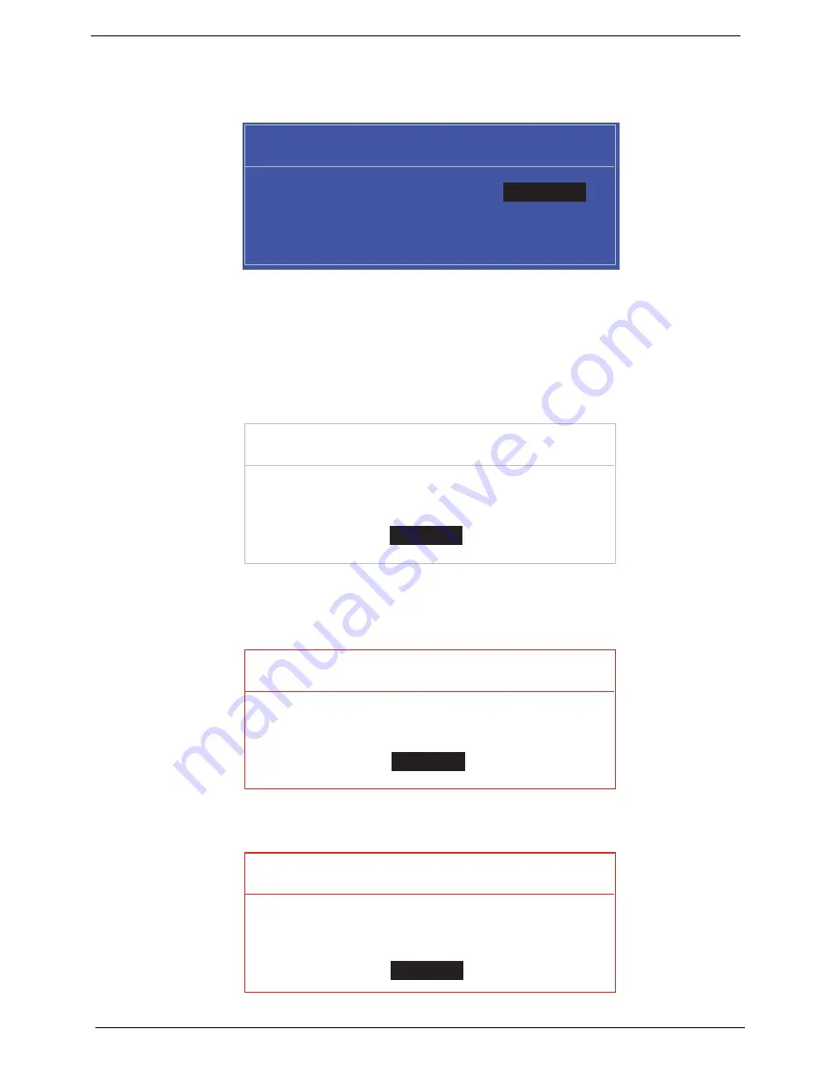
If the verification is OK, the screen will display as following.
The password setting is complete after the user presses
Enter
.
If the current password entered does not match the actual current password, the screen will show you the
Setup Warning.
If the new password and confirm new password strings do not match, the screen displays the following
message.
S e t S u p e r v i s o r P a s s w o r d
E n t e r C u r r e n t P a s s w o r d [ ]
[ ]
E n t e r N e w P a s s w o r d [ ]
C o n f i r m N e w P a s s w o r d [ ]
[ ]
S e t u p N o t i c e
C h a n g e s h a v e b e e n s a v e d .
[ C o n t i n u e ]
[
C o n t i n u e
]
S e t u p W a r n i n g
I n v a l i d P a s s w o r d .
[ C o n t i n u e ]
[
C o n t i n u e
]
S e t u p W a r n i n g
P a s s w o r d s d o n o t m a t c h .
R e - e n t e r p a s s w o r d .
[ C o n t i n u e ]
[
C o n t i n u e
]
Summary of Contents for eMachines E628 Series
Page 6: ...VI ...
Page 10: ...X Table of Contents ...
Page 51: ...Chapter 2 41 ...
Page 64: ...Chapter 3 54 8 Remove the DIMM ...
Page 67: ...57 Chapter 3 6 Remove the WLAN Board from the Mainboard ...
Page 79: ...69 Chapter 3 4 Slide the Touchpad Bracket out from the slots in the upper cover ...
Page 96: ...Chapter 3 86 4 Lift the fan away from the Mainboard ...
Page 102: ...Chapter 3 92 7 Lift up the bezel and remove it from the LCD Module ...
Page 109: ...99 Chapter 3 5 Lift the Microphone Module upward to detach the adhesive holding it in place ...
Page 156: ...Chapter 3 146 2 Slide the battery lock unlock latch to the lock position ...
Page 157: ...147 Chapter 3 ...
Page 199: ...Chapter 6 189 ...
Page 215: ...205 Appendix A ...
Page 224: ...214 ...