


16
Chapter 1
Using the System Utilities
Acer GridVista (dual-display compatible)
NOTE:
This feature is only available on certain models.
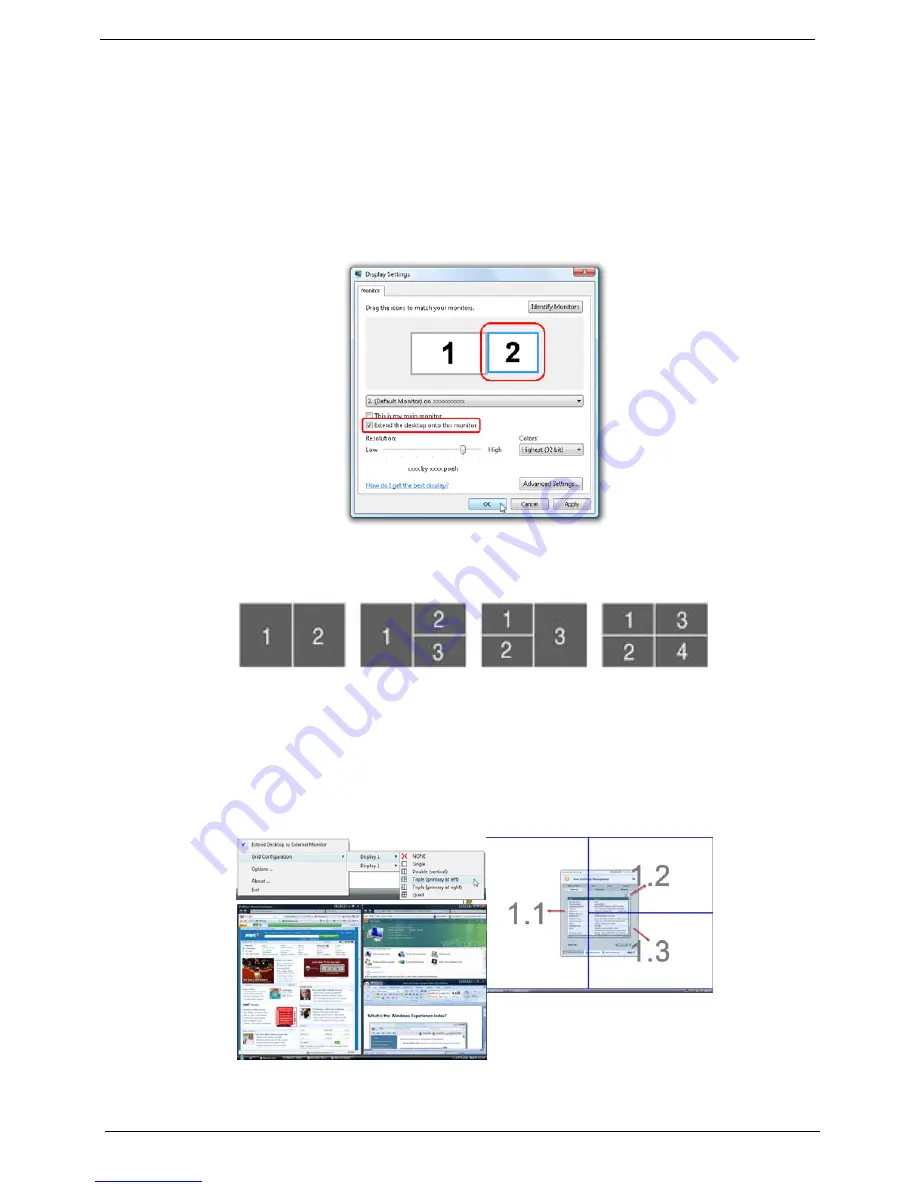
To enable the dual monitor feature of the notebook, first ensure that the second monitor is connected, then
select
Start, Control Panel, Display
and click on
Settings
. Select the secondary monitor
(2)
icon in the
display box and then click the check box
Extend my windows desktop onto this monitor
. Finally, click
Apply
to confirm the new settings and click
OK
to complete the process.
Acer GridVista is a handy utility that offers four pre-defined display settings so you can view multiple windows
on the same screen. To access this function, please go to
Start
´
All Programs
and click on
Acer GridVista
.
You may choose any one of the four display settings indicated below:
Double (vertical), Triple (primary at left), Triple (primary at right), or Quad Acer Gridvista is dual-display
compatible, allowing two displays to be partitioned independently.
Acer Gridvista is dual-display compatible, allowing two displays to be partitioned independently.
AcerGridVista is simple to set up:
1.
Run Acer GridVista and select your preferred screen configuration for each display from the task bar.
2.
Drag and drop each window into the appropriate grid.
3.
Enjoy the convenience of a well-organized desktop.
NOTE:
Please ensure that the resolution setting of the second monitor is set to the manufacturer's
recommended value.
Summary of Contents for Aspire Z5751
Page 6: ...VI ...
Page 10: ...X Table of Contents ...
Page 14: ...4 Chapter 1 System Block Diagram ...
Page 34: ...24 Chapter 1 ...
Page 72: ...62 Chapter 3 4 Disconnect the following four cables from the Mainboard A B C D ...
Page 85: ...Chapter 3 75 4 Using both hands lift the Thermal Module clear of the Mainboard ...
Page 87: ...Chapter 3 77 4 Lift the CPU Fan clear of the Mainboard as shown ...
Page 93: ...Chapter 3 83 5 Lift the LCD Panel clear of the module ...
Page 101: ...Chapter 3 91 9 The Antennas and cables appear as shown when correctly installed ...
Page 106: ...96 Chapter 3 2 Replace the four screws and screw caps provided ...
Page 111: ...Chapter 3 101 5 Replace the FFC and press down as indicated to secure it to the Upper Cover ...
Page 122: ...112 Chapter 3 17 Replace the two screws securing the LCD Module to the Lower Cover ...
Page 130: ...120 Chapter 3 ...
Page 154: ...144 Chapter 5 ...
Page 156: ...146 Chapter 6 Aspire 5517 Exploded Diagrams Main Assembly 1 2 3 4 5 ...
Page 169: ...Chapter 6 159 ...
Page 178: ...168 Appendix C ...
Page 182: ...172 ...


