


10
Chapter 1
Indicators
The computer has several easy-to-read status indicators. The front panel indicators are visible even when the
computer cover is closed.
NOTE:
1.
Charging:
The light shows amber when the battery is charging. 2.
Fully charged:
The light shows
green when in AC mode.
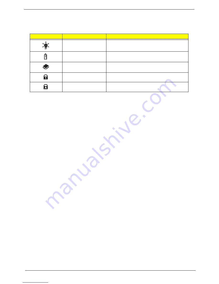
Icon
Function
Description
Power
Indicates the computer's power status.
Battery
Indicates the computer's battery status.
HDD
Indicates when the hard disk drive is active.
Num Lock
Lights up when Num Lock is activated.
Caps Lock
Lights up when Caps Lock is activated.
Summary of Contents for Aspire Z5751
Page 6: ...VI ...
Page 10: ...X Table of Contents ...
Page 14: ...4 Chapter 1 System Block Diagram ...
Page 34: ...24 Chapter 1 ...
Page 72: ...62 Chapter 3 4 Disconnect the following four cables from the Mainboard A B C D ...
Page 85: ...Chapter 3 75 4 Using both hands lift the Thermal Module clear of the Mainboard ...
Page 87: ...Chapter 3 77 4 Lift the CPU Fan clear of the Mainboard as shown ...
Page 93: ...Chapter 3 83 5 Lift the LCD Panel clear of the module ...
Page 101: ...Chapter 3 91 9 The Antennas and cables appear as shown when correctly installed ...
Page 106: ...96 Chapter 3 2 Replace the four screws and screw caps provided ...
Page 111: ...Chapter 3 101 5 Replace the FFC and press down as indicated to secure it to the Upper Cover ...
Page 122: ...112 Chapter 3 17 Replace the two screws securing the LCD Module to the Lower Cover ...
Page 130: ...120 Chapter 3 ...
Page 154: ...144 Chapter 5 ...
Page 156: ...146 Chapter 6 Aspire 5517 Exploded Diagrams Main Assembly 1 2 3 4 5 ...
Page 169: ...Chapter 6 159 ...
Page 178: ...168 Appendix C ...
Page 182: ...172 ...


