


Chapter 4
123
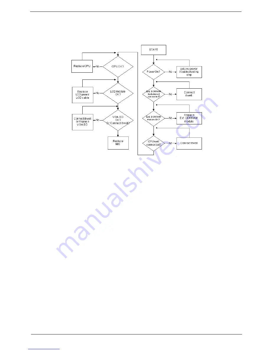
No Display Issue
If the
Display
doesn’t work, perform the following actions one at a time to correct the problem. Do not replace
a non-defective FRUs:
No POST or Video
If the POST or video doesn’t display, perform the following actions one at a time to correct the problem.
1.
Make sure that the internal display is selected. On this notebook model, switching between the internal
display and the external display is done by pressing
Fn+F5
. Reference Product pages for specific model
procedures.
2.
Make sure the computer has power by checking at least one of the following occurs:
•
Fans start up
•
Status LEDs light up
If there is no power, see “Power On Issue” on page 122.
3.
Drain any stored power by removing the power cable and battery and holding down the power button for
10 seconds. Reconnect the power and reboot the computer.
4.
Connect an external monitor to the computer and switch between the internal display and the external
display is by pressing
Fn+F5
(on this model).
If the POST or video appears on the external display, see “LCD Failure” on page 125.
5.
Disconnect power and all external devices including port replicators or docking stations. Remove any
memory cards and CD/DVD discs. Restart the computer.
If the computer boots correctly, add the devices one by one until the failure point is discovered.
6.
Reseat the memory modules.
7.
Remove the drives (see “Disassembly Process” on page 42).
8.
If the Issue is still not resolved, see “Online Support Information” on page 167.
Summary of Contents for Aspire Z5751
Page 6: ...VI ...
Page 10: ...X Table of Contents ...
Page 14: ...4 Chapter 1 System Block Diagram ...
Page 34: ...24 Chapter 1 ...
Page 72: ...62 Chapter 3 4 Disconnect the following four cables from the Mainboard A B C D ...
Page 85: ...Chapter 3 75 4 Using both hands lift the Thermal Module clear of the Mainboard ...
Page 87: ...Chapter 3 77 4 Lift the CPU Fan clear of the Mainboard as shown ...
Page 93: ...Chapter 3 83 5 Lift the LCD Panel clear of the module ...
Page 101: ...Chapter 3 91 9 The Antennas and cables appear as shown when correctly installed ...
Page 106: ...96 Chapter 3 2 Replace the four screws and screw caps provided ...
Page 111: ...Chapter 3 101 5 Replace the FFC and press down as indicated to secure it to the Upper Cover ...
Page 122: ...112 Chapter 3 17 Replace the two screws securing the LCD Module to the Lower Cover ...
Page 130: ...120 Chapter 3 ...
Page 154: ...144 Chapter 5 ...
Page 156: ...146 Chapter 6 Aspire 5517 Exploded Diagrams Main Assembly 1 2 3 4 5 ...
Page 169: ...Chapter 6 159 ...
Page 178: ...168 Appendix C ...
Page 182: ...172 ...


