


115
Chapter 6
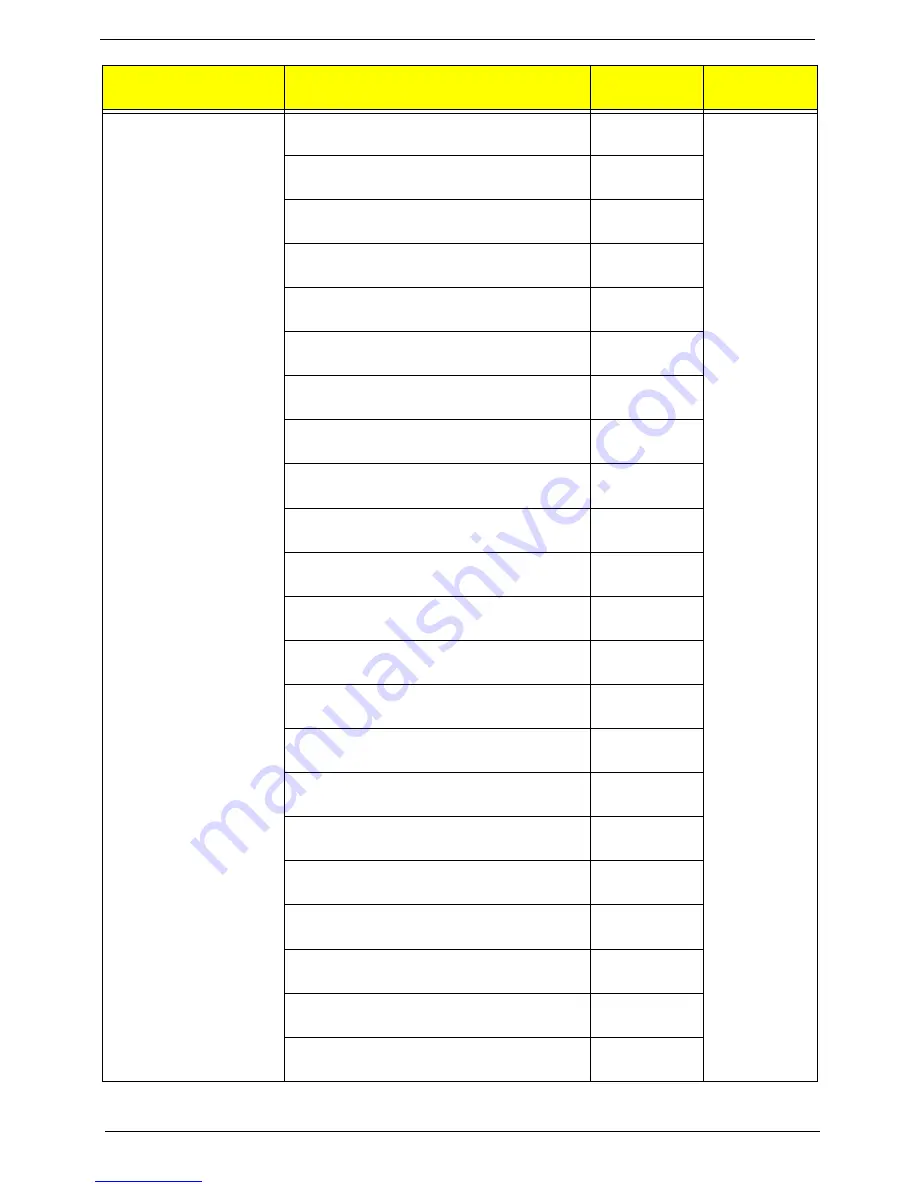
Keyboard PRIMAX KB36211 USB Black Icelandic
with new acer logo
KB.USB0P.236
Keyboard PRIMAX KB36211 USB Black
Norwegian with new acer logo
KB.USB0P.237
Keyboard PRIMAX KB36211 USB Black Hebrew
with new acer logo
KB.USB0P.238
Keyboard PRIMAX KB36211 USB Black Polish
with new acer logo
KB.USB0P.239
Keyboard PRIMAX KB36211 USB Black Slovenian
with new acer logo
KB.USB0P.240
Keyboard PRIMAX KB36211 USB Black Slovak
with new acer logo
KB.USB0P.241
Keyboard PRIMAX KB36211 USB Black Russian
with new acer logo
KB.USB0P.242
Keyboard PRIMAX KB36211 USB Black
Hungarian with new acer logo
KB.USB0P.243
Keyboard PRIMAX KB36211 USB Black Greek
with new acer logo
KB.USB0P.244
Keyboard PRIMAX KB36211 USB Black Danish
with new acer logo
KB.USB0P.245
Keyboard PRIMAX KB36211 USB Black Czech
with new acer logo
KB.USB0P.246
Keyboard PRIMAX KB36211 USB Black
Romanian with new acer logo
KB.USB0P.247
Keyboard PRIMAX KB36211 USB Black Turkish
with new acer logo
KB.USB0P.248
Keyboard PRIMAX KB36211 USB Black Turkish-Q
with new acer logo
KB.USB0P.249
Keyboard PRIMAX KB36211 USB Black Arabic/
French with new acer logo
KB.USB0P.250
Keyboard PRIMAX KB36211 USB Black Kazakh
with new acer logo
KB.USB0P.251
Keyboard PRIMAX KB36211 USB Black Turkmen
with new acer logo
KB.USB0P.252
Keyboard PRIMAX KB36211 USB Black Nordic
with new acer logo
KB.USB0P.253
Keyboard PRIMAX KB36211 USB Black English/
Canadian French with new acer logo
KB.USB0P.254
Keyboard PRIMAX KB36211 USB Black Czech/
Slovak with new acer logo
KB.USB0P.255
Keyboard PRIMAX KB36211 USB Black Swiss/FR
with new acer logo
KB.USB0P.256
Keyboard PRIMAX KB36211 USB Black Korean
with new acer logo
KB.USB0P.257
Category
Part Number
Acer P/N
Exploded
Diagram Item
Summary of Contents for Aspire M3985
Page 1: ...Acer Aspire M3985 Service Guide PRINTED IN TAIWAN ...
Page 13: ...Chapter 1 5 Block Diagram ...
Page 46: ...38 Chapter 3 4 Pull the Pull the optical drive out of the chassis ...
Page 50: ...42 Chapter 3 7 Lift the power supply module out of the chassis ...
Page 53: ...Chapter 3 45 3 Lift the board from the chassis 4 Punching in IO Shield then you can remove it ...
Page 69: ...Chapter 3 61 Reinstalling the I O Shielding 1 Install I O shielding into chassis ...
Page 77: ...Chapter 3 69 3 Close the PCI Latch fix the three screws ...
Page 80: ...72 Chapter 3 3 Connect the cooler cable to the main board connector ...
Page 83: ...Chapter 3 75 Reinstalling the Side Panel 1 Install the side Panel then fix two screws ...
Page 91: ...83 Chapter 4 b Select Proceed with flash update and Press Enter ...