


System Utilities
2-29
To write the MAC address,
1.
Create a DOS bootable USB HDD.
2.
Copy the contents of the MAC folder to the HDD and remove the HDD form the computer.
3.
Reboot the computer and press
F2
during the boot sequence to enter the setup menu.
4.
Select the Boot menu item and move the entry “USB HDD” to the first position. Refer to
Boot.
5.
Insert the USB HDD and reboot the computer.
6.
At the command prompt, navigate to the MAC folder.
7.
Execute <
WriteMAC.bat
>.
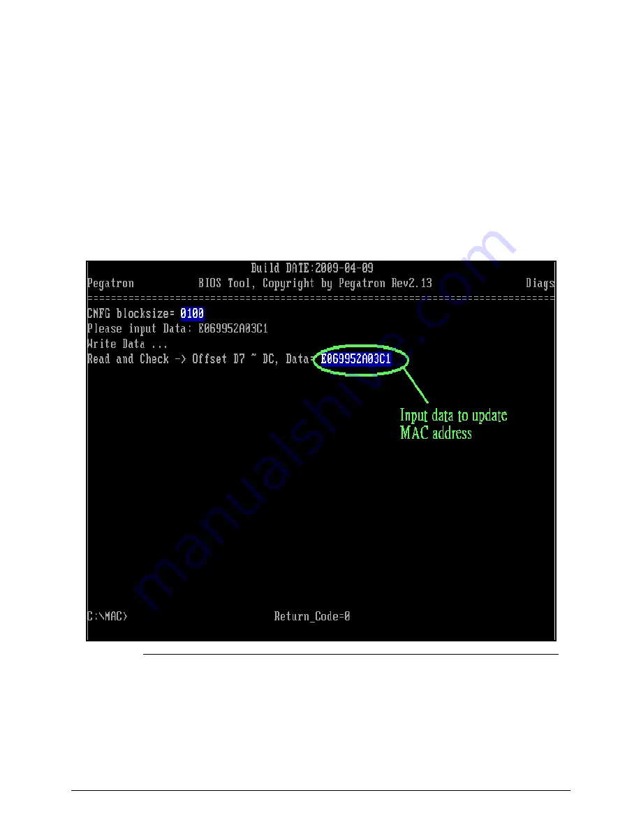
8.
At prompt type in MAC address.
9.
Press
Enter
(Figure 2-31).
10. Reboot when the process has completed.
Figure 2-32.
Write LAN MAC address
Summary of Contents for Aspire 7739
Page 36: ...1 40 Hardware Specifications and Configurations ...
Page 64: ...2 30 System Utilities ...
Page 71: ...3 11 Figure 3 7 HDD Module Figure 3 8 HDD Module 3 Remove HDD follow the arrowhead ...
Page 72: ...3 12 Figure 3 9 HDD Module Figure 3 10 HDD Module ...
Page 74: ...3 14 Figure 3 13 WLAN Module ...
Page 77: ...3 17 Figure 3 19 Memory Module Figure 3 20 Memory Module Figure 3 21 Memory Module ...
Page 82: ...3 22 ...
Page 86: ...3 26 Figure 3 35 TOP Case Figure 3 36 TOP Case ...
Page 89: ...3 29 Figure 3 42 I O BD Figure 3 43 I O BD ...
Page 91: ...3 31 Figure 3 46 Mother board Figure 3 47 Mother board 3 Take out the RTC battery ...
Page 92: ...3 32 Figure 3 48 RTC BATTERY Figure 3 49 RTC BATTERY ...
Page 94: ...3 34 Figure 3 51 Thermal Figure 3 52 Thermal Figure 3 53 Thermal ...
Page 103: ...3 43 Figure 3 71 LCD Panel Figure 3 72 LCD Panel 4 Put camera and MIC in the right place ...
Page 104: ...3 44 Figure 3 73 LCD Panel Figure 3 74 LCD Panel ...
Page 107: ...3 47 Figure 3 79 Hinge ...
Page 109: ...3 49 Figure 3 82 Thermal Module Figure 3 83 Thermal Module ...
Page 111: ...3 51 Figure 3 86 Main board Figure 3 87 Main board ...
Page 113: ...3 53 Figure 3 90 ODD BD Figure 3 91 ODD BD 2 Connect IO BD and ODD B D FFC CONN ...
Page 114: ...3 54 Figure 3 92 IO BD Figure 3 93 ODD BD ...
Page 117: ...3 57 Figure 3 98 Top case Figure 3 99 Top case ...
Page 119: ...3 59 Figure 3 102 Top case Figure 3 103 Top case Figure 3 104 Top case ...
Page 124: ...3 64 Figure 3 113 ...
Page 128: ...3 68 Figure 3 120 Battery ...
Page 154: ...4 28 Troubleshooting ...
Page 186: ...6 28 FRU Field Replaceable Unit List ...