


Troubleshooting
4-3
Troubleshooting
Introduction
0
This chapter contains information about troubleshooting common problems associated with
the notebook.
General Information
0
The following procedures are a guide for troubleshooting computer problems. The step by
step procedures are designed to be performed as described.
NOTE:
NOTE
:
The diagnostic tests are intended for Acer products only. Non-Acer products, prototype
cards, or modified options can give false errors and invalid system responses.
1.
Obtain as much detailed information as possible about the problem.
2.
If possible, verify the symptoms by re-creating the failure through diagnostic tests or
repeating the operation that led to the problem.
3.
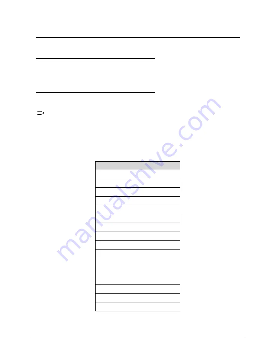
Use Table 4-1 with the verified symptom to determine the solution.
4.
If the Issue is still not resolved, refer to
Online Support Information
.
Table 4-1.
Common Problems
Symptoms (Verified)
Power On Issues
No Display Issues
LCD Failure
Keyboard Failure
Touchpad Failure
Internal & External Speaker Failure
Microphone Failure
USB Failure
WLAN Failure
Card Reader Failure
Thermal Unit Failure
HDMI and CRT Failure
CD-ROM/DVD Failure
Other Functions Failure
Intermittent Problems
Undetermined Problems
Summary of Contents for Aspire 7739
Page 36: ...1 40 Hardware Specifications and Configurations ...
Page 64: ...2 30 System Utilities ...
Page 71: ...3 11 Figure 3 7 HDD Module Figure 3 8 HDD Module 3 Remove HDD follow the arrowhead ...
Page 72: ...3 12 Figure 3 9 HDD Module Figure 3 10 HDD Module ...
Page 74: ...3 14 Figure 3 13 WLAN Module ...
Page 77: ...3 17 Figure 3 19 Memory Module Figure 3 20 Memory Module Figure 3 21 Memory Module ...
Page 82: ...3 22 ...
Page 86: ...3 26 Figure 3 35 TOP Case Figure 3 36 TOP Case ...
Page 89: ...3 29 Figure 3 42 I O BD Figure 3 43 I O BD ...
Page 91: ...3 31 Figure 3 46 Mother board Figure 3 47 Mother board 3 Take out the RTC battery ...
Page 92: ...3 32 Figure 3 48 RTC BATTERY Figure 3 49 RTC BATTERY ...
Page 94: ...3 34 Figure 3 51 Thermal Figure 3 52 Thermal Figure 3 53 Thermal ...
Page 103: ...3 43 Figure 3 71 LCD Panel Figure 3 72 LCD Panel 4 Put camera and MIC in the right place ...
Page 104: ...3 44 Figure 3 73 LCD Panel Figure 3 74 LCD Panel ...
Page 107: ...3 47 Figure 3 79 Hinge ...
Page 109: ...3 49 Figure 3 82 Thermal Module Figure 3 83 Thermal Module ...
Page 111: ...3 51 Figure 3 86 Main board Figure 3 87 Main board ...
Page 113: ...3 53 Figure 3 90 ODD BD Figure 3 91 ODD BD 2 Connect IO BD and ODD B D FFC CONN ...
Page 114: ...3 54 Figure 3 92 IO BD Figure 3 93 ODD BD ...
Page 117: ...3 57 Figure 3 98 Top case Figure 3 99 Top case ...
Page 119: ...3 59 Figure 3 102 Top case Figure 3 103 Top case Figure 3 104 Top case ...
Page 124: ...3 64 Figure 3 113 ...
Page 128: ...3 68 Figure 3 120 Battery ...
Page 154: ...4 28 Troubleshooting ...
Page 186: ...6 28 FRU Field Replaceable Unit List ...