


4-4
Troubleshooting
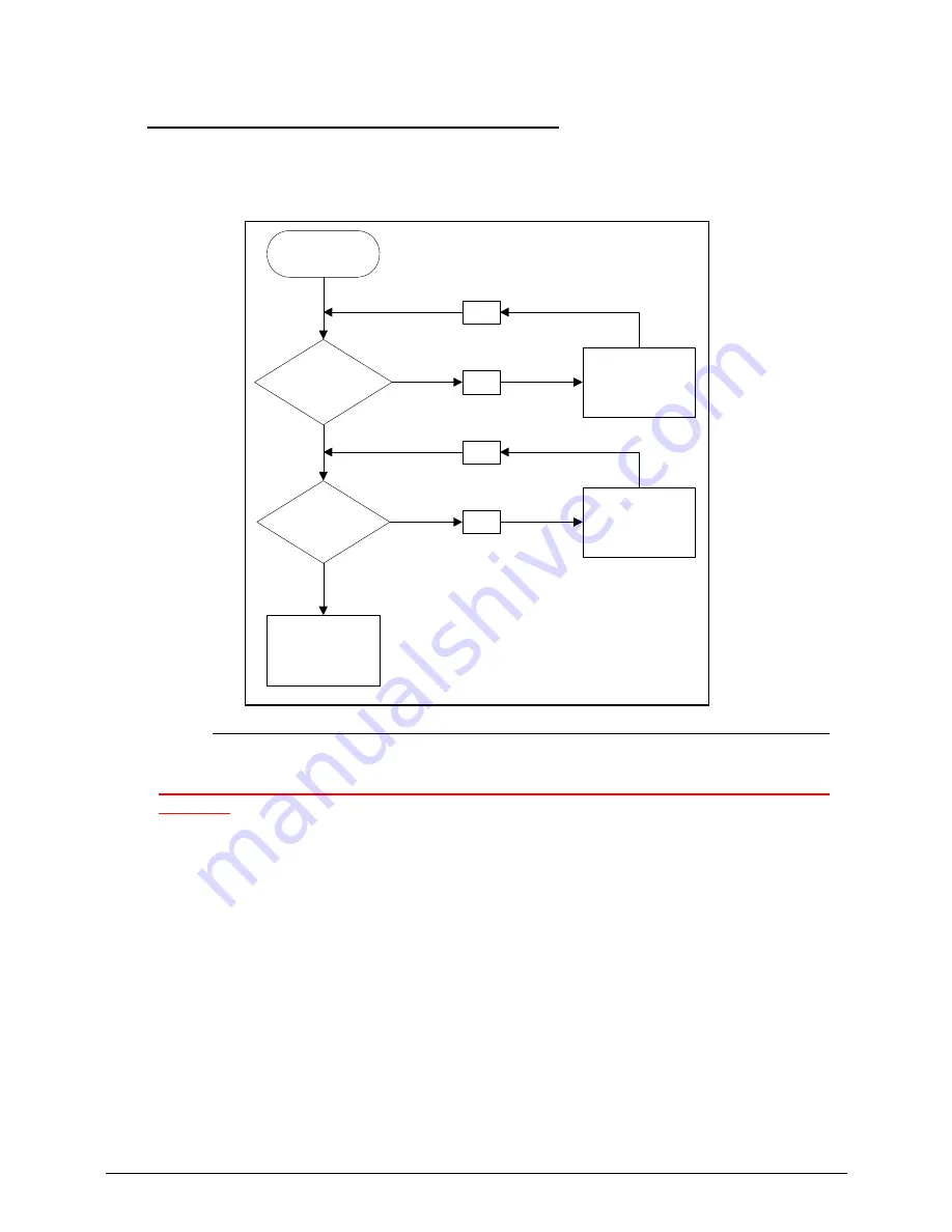
Power On Issues
0
If the system does not power on, perform the following, one at a time, to correct the problem. Do not
replace a non-defective FRU:
Figure 4-1.
Power On Issue
Please wait for 3 min. after removing all power (AC adapter and Battery), then re-insert to try
power on.
Computer Shuts Down Intermittently
0
If the system powers off at intervals, perform the following.
1.
Makes sure the power cable is properly connected to the computer and the electrical
outlet.
2.
Remove all extension cables between the computer and the outlet.
3.
Remove all surge protectors between the computer and the electrical outlet. Plug the
computer directly into a known serviceable electrical outlet.
4.
Disconnect the power and open the casing to check the Thermal Unit (refer to Thermal
Unit Failure) and fan airways are free of obstructions.
5.
Remove all external and non-essential hardware connected to the computer that are not
necessary to boot the computer to the failure point.
6.
Remove any recently installed software.
7.
If the Issue is still not resolved, refer to
Online Support Information
.
Start
Check
AC/Battery
Power on
Check
Daughter BD &
FFC
NG
OK
Swap AC/Battery
Swap
Daughter BD
& Re-plug PWR
FFC
NG
OK
Swap MB
Summary of Contents for Aspire 7739
Page 36: ...1 40 Hardware Specifications and Configurations ...
Page 64: ...2 30 System Utilities ...
Page 71: ...3 11 Figure 3 7 HDD Module Figure 3 8 HDD Module 3 Remove HDD follow the arrowhead ...
Page 72: ...3 12 Figure 3 9 HDD Module Figure 3 10 HDD Module ...
Page 74: ...3 14 Figure 3 13 WLAN Module ...
Page 77: ...3 17 Figure 3 19 Memory Module Figure 3 20 Memory Module Figure 3 21 Memory Module ...
Page 82: ...3 22 ...
Page 86: ...3 26 Figure 3 35 TOP Case Figure 3 36 TOP Case ...
Page 89: ...3 29 Figure 3 42 I O BD Figure 3 43 I O BD ...
Page 91: ...3 31 Figure 3 46 Mother board Figure 3 47 Mother board 3 Take out the RTC battery ...
Page 92: ...3 32 Figure 3 48 RTC BATTERY Figure 3 49 RTC BATTERY ...
Page 94: ...3 34 Figure 3 51 Thermal Figure 3 52 Thermal Figure 3 53 Thermal ...
Page 103: ...3 43 Figure 3 71 LCD Panel Figure 3 72 LCD Panel 4 Put camera and MIC in the right place ...
Page 104: ...3 44 Figure 3 73 LCD Panel Figure 3 74 LCD Panel ...
Page 107: ...3 47 Figure 3 79 Hinge ...
Page 109: ...3 49 Figure 3 82 Thermal Module Figure 3 83 Thermal Module ...
Page 111: ...3 51 Figure 3 86 Main board Figure 3 87 Main board ...
Page 113: ...3 53 Figure 3 90 ODD BD Figure 3 91 ODD BD 2 Connect IO BD and ODD B D FFC CONN ...
Page 114: ...3 54 Figure 3 92 IO BD Figure 3 93 ODD BD ...
Page 117: ...3 57 Figure 3 98 Top case Figure 3 99 Top case ...
Page 119: ...3 59 Figure 3 102 Top case Figure 3 103 Top case Figure 3 104 Top case ...
Page 124: ...3 64 Figure 3 113 ...
Page 128: ...3 68 Figure 3 120 Battery ...
Page 154: ...4 28 Troubleshooting ...
Page 186: ...6 28 FRU Field Replaceable Unit List ...