


1-16
Hardware Specifications and Configurations
Indicators
0
The computer has several easy-to-read status indicators. The following indicators are visible
even when the computer cover is closed.
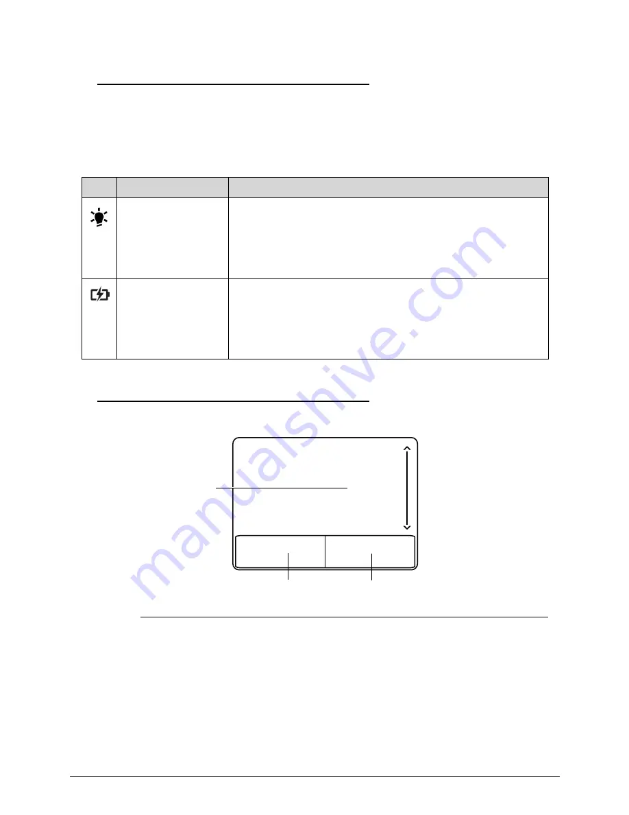
Touchpad Basics
0
Figure 1-5. Touchpad
Move finger across the TouchPad (1) to move the cursor.
Press the left (2) and right (3) buttons located beneath the TouchPad to perform selection and
execution functions. These two buttons are the equivalent of the left and right buttons on a
mouse. Tapping on the TouchPad is the same as clicking the left button.
Table 1-5. Indicators
Icon
Function
Description
System state
indicator
Indicates the computer’s power status:
Power on: Blue
Standby: Breeze mode Blue(1sec on/3 sec off)
Entering Hibernation: Blinking mode Blue(1 sec on/1 sec off)
Hibernation/Power off: N/A
Battery state
Indicator
Full Charged: Blue
Under Charging: Orange
Battery low: Breeze mode Orange(1 sec on/3 sec off)
Battery situation: Blinking mode Orange(1 sec on/1 sec off)
Using battery or not connected to AC power:N/A.
1
3
2
Summary of Contents for Aspire 7739
Page 36: ...1 40 Hardware Specifications and Configurations ...
Page 64: ...2 30 System Utilities ...
Page 71: ...3 11 Figure 3 7 HDD Module Figure 3 8 HDD Module 3 Remove HDD follow the arrowhead ...
Page 72: ...3 12 Figure 3 9 HDD Module Figure 3 10 HDD Module ...
Page 74: ...3 14 Figure 3 13 WLAN Module ...
Page 77: ...3 17 Figure 3 19 Memory Module Figure 3 20 Memory Module Figure 3 21 Memory Module ...
Page 82: ...3 22 ...
Page 86: ...3 26 Figure 3 35 TOP Case Figure 3 36 TOP Case ...
Page 89: ...3 29 Figure 3 42 I O BD Figure 3 43 I O BD ...
Page 91: ...3 31 Figure 3 46 Mother board Figure 3 47 Mother board 3 Take out the RTC battery ...
Page 92: ...3 32 Figure 3 48 RTC BATTERY Figure 3 49 RTC BATTERY ...
Page 94: ...3 34 Figure 3 51 Thermal Figure 3 52 Thermal Figure 3 53 Thermal ...
Page 103: ...3 43 Figure 3 71 LCD Panel Figure 3 72 LCD Panel 4 Put camera and MIC in the right place ...
Page 104: ...3 44 Figure 3 73 LCD Panel Figure 3 74 LCD Panel ...
Page 107: ...3 47 Figure 3 79 Hinge ...
Page 109: ...3 49 Figure 3 82 Thermal Module Figure 3 83 Thermal Module ...
Page 111: ...3 51 Figure 3 86 Main board Figure 3 87 Main board ...
Page 113: ...3 53 Figure 3 90 ODD BD Figure 3 91 ODD BD 2 Connect IO BD and ODD B D FFC CONN ...
Page 114: ...3 54 Figure 3 92 IO BD Figure 3 93 ODD BD ...
Page 117: ...3 57 Figure 3 98 Top case Figure 3 99 Top case ...
Page 119: ...3 59 Figure 3 102 Top case Figure 3 103 Top case Figure 3 104 Top case ...
Page 124: ...3 64 Figure 3 113 ...
Page 128: ...3 68 Figure 3 120 Battery ...
Page 154: ...4 28 Troubleshooting ...
Page 186: ...6 28 FRU Field Replaceable Unit List ...