


2-10
System Utilities
3.
Press
Enter
twice without typing anything in the Enter New Password and Confirm New
Password fields. The computer then sets the Supervisor Password parameter to Clear.
4.
Press
F10
to save changes and exit the BIOS Setup Utility.
Changing a Password
0
1.
Use the
↑
and
↓
keys to highlight Set Supervisor Password and press the
Enter
. The Set
Supervisor Password box appears.
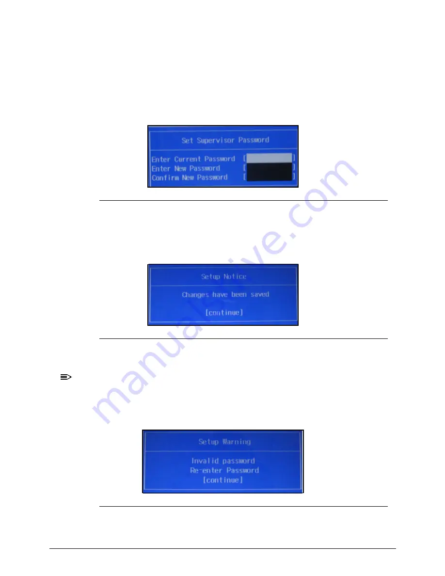
Figure 2-6.
Set Supervisor Password
2.
Type the current password in the Enter Current Password field and press
Enter
.
3.
Type a password in the Enter New Password field. Retype the password in the Confirm
New Password field.
Figure 2-7.
Setup Notice
4.
Press
Enter
. The computer sets User Password parameter to Set.
NOTE:
NOTE
:
Users can enable the Password on boot parameter.
5.
Press
F10
to save changes and exit the BIOS Setup Utility.
If the verification is OK, the screen will show as following.
Figure 2-8.
This Setup Warning
The password setting is complete after the user presses
Enter
.
Summary of Contents for Aspire 7739
Page 36: ...1 40 Hardware Specifications and Configurations ...
Page 64: ...2 30 System Utilities ...
Page 71: ...3 11 Figure 3 7 HDD Module Figure 3 8 HDD Module 3 Remove HDD follow the arrowhead ...
Page 72: ...3 12 Figure 3 9 HDD Module Figure 3 10 HDD Module ...
Page 74: ...3 14 Figure 3 13 WLAN Module ...
Page 77: ...3 17 Figure 3 19 Memory Module Figure 3 20 Memory Module Figure 3 21 Memory Module ...
Page 82: ...3 22 ...
Page 86: ...3 26 Figure 3 35 TOP Case Figure 3 36 TOP Case ...
Page 89: ...3 29 Figure 3 42 I O BD Figure 3 43 I O BD ...
Page 91: ...3 31 Figure 3 46 Mother board Figure 3 47 Mother board 3 Take out the RTC battery ...
Page 92: ...3 32 Figure 3 48 RTC BATTERY Figure 3 49 RTC BATTERY ...
Page 94: ...3 34 Figure 3 51 Thermal Figure 3 52 Thermal Figure 3 53 Thermal ...
Page 103: ...3 43 Figure 3 71 LCD Panel Figure 3 72 LCD Panel 4 Put camera and MIC in the right place ...
Page 104: ...3 44 Figure 3 73 LCD Panel Figure 3 74 LCD Panel ...
Page 107: ...3 47 Figure 3 79 Hinge ...
Page 109: ...3 49 Figure 3 82 Thermal Module Figure 3 83 Thermal Module ...
Page 111: ...3 51 Figure 3 86 Main board Figure 3 87 Main board ...
Page 113: ...3 53 Figure 3 90 ODD BD Figure 3 91 ODD BD 2 Connect IO BD and ODD B D FFC CONN ...
Page 114: ...3 54 Figure 3 92 IO BD Figure 3 93 ODD BD ...
Page 117: ...3 57 Figure 3 98 Top case Figure 3 99 Top case ...
Page 119: ...3 59 Figure 3 102 Top case Figure 3 103 Top case Figure 3 104 Top case ...
Page 124: ...3 64 Figure 3 113 ...
Page 128: ...3 68 Figure 3 120 Battery ...
Page 154: ...4 28 Troubleshooting ...
Page 186: ...6 28 FRU Field Replaceable Unit List ...