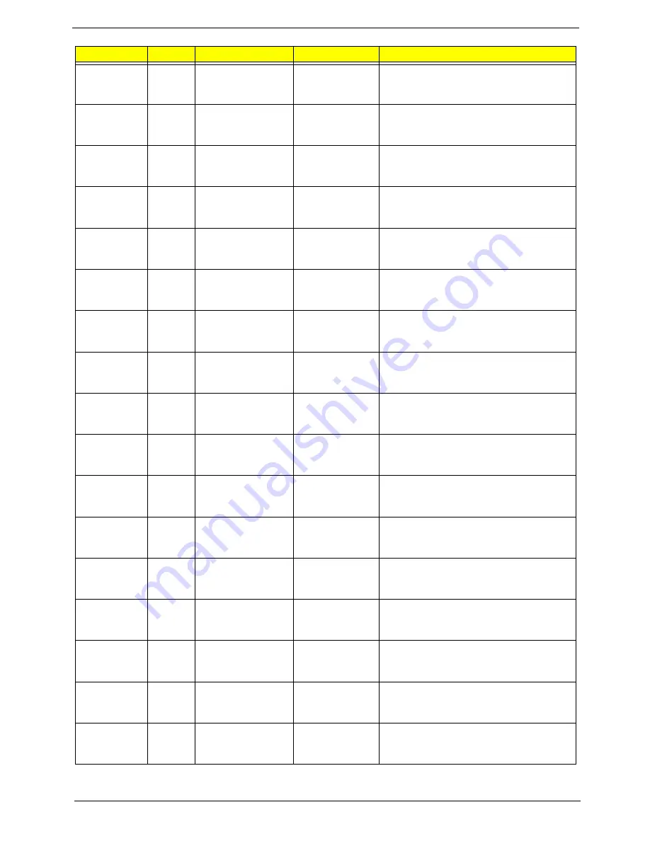
Acer Aspire 6530 Series Service Manual Download Page 175

165

Appendix A

AS6530-
702G25Mn 

PA

Canada

LX.AUQ0X.008

AS6530-702G25Mn VHP32ATCA2 MC 
UMACO 1*2G/250/6L/
CB_bgn_0.3D_HG_FR31

AS6530-
702G25Mn 

PA

USA

LX.AUQ0X.006

AS6530-702G25Mn VHP32ATUS1 MC 
UMACO 1*2G/250/6L/
CB_bgn_0.3D_HG_EN32

AS6530-
702G25Mn 

PA

ACLA-Spanish

LX.AUQ0X.001

AS6530-702G25Mn VHP32ATEA1 MC 
UMACO 1*2G/250/6L/
CB_bgn_0.3D_HG_ES21

AS6530-
702G25Mn 

PA

ACLA-Portuguese

LX.AUQ0X.017

AS6530-702G25Mn VHP32ATXC1 MC 
UMACO 1*2G/250/6L/
CB_bgn_0.3D_HG_XC21

AS6530-
602G16Mi 

AAP

Japan

LX.AUQ0X.018

AS6530-602G16Mi VHP32AJP1 MC 
UMACO 1*2G/160/6L/5R/
CB_bg_0.3D_HG_JA12_W6F

AS6530-
602G16Mi 

AAP

Japan

LX.AUQ0X.019

AS6530-602G16Mi VHP32AJP1 MC 
UMACO 1*2G/160/6L/5R/
CB_bg_0.3D_HG_JA11_H6A

AS6530-
603G25Mn 

PA

Canada

LX.AUQ0X.022

AS6530-603G25Mn VHP32ATCA2 MC 
UMACO 2G+1G/250/6L/
CB_bgn_0.3D_HG_FR31

AS6530-
604G16Mn 

PA

Canada

LX.AUQ0X.023

AS6530-604G16Mn VHP32ACA2 MC 
UMACO 2*2G/160/6L/
CB_bgn_0.3D_HG_FR31

AS6530-
601G16Mn 

TWN

GCTWN

LX.AUQ0Y.003

AS6530-601G16Mn VHB32ATTW1 MC 
UMACO 1*1G/160/BT/6L/5R/
CB_bgn_0.3D_HG_TC11

AS6530-
703G32Mn 

PA

Canada

LX.AUQ0X.026

AS6530-703G32Mn VHP32ATCA1 MC 
UMACO 2G+1G/320/6L/5R/
CB_bgn_0.3D_HG_FR11

AS6530-
703G32Mn 

PA

Canada

LX.AUQ0X.027

AS6530-703G32Mn VHP32ATCA2 MC 
UMACO 2G+1G/320/6L/5R/
CB_bgn_0.3D_HG_FR31

AS6530-
703G32Mn 

PA

Canada

LX.AUQ0X.028

AS6530-703G32Mn VHP32ATCA2 MC 
UMACO 2G+1G/320/6L/5R/
CB_bgn_0.3D_HG_FR33

AS6530-
703G32Mn 

PA

Canada

LX.AUQ0X.029

AS6530-703G32Mn VHP32ATCA2 MC 
UMACO 2G+1G/320/6L/5R/
CB_bgn_0.3D_HG_FR35

AS6530-
703G32Mn 

PA

USA

LX.AUQ0X.025

AS6530-703G32Mn VHP32ATUS1 MC 
UMACO 2G+1G/320/6L/5R/
CB_bgn_0.3D_HG_EN33

AS6530-
703G32Mn 

PA

USA

LX.AUQ0X.024

AS6530-703G32Mn VHP32ATUS1 MC 
UMACO 2G+1G/320/6L/5R/
CB_bgn_0.3D_HG_EN32

AS6530-
703G32Mn 

PA

Canada

LX.AUQ0X.030

AS6530-703G32Mn VHP32ATCA2 MC 
UMACO 2G+1G/320/6L/
CB_bgn_0.3D_HG_FR31

AS6530-
602G16Mn 

TWN

GCTWN

LX.AUQ0Y.005

AS6530-602G16Mn VHB32ATTW1 MC 
UMACO 1*2G/160/BT/6L/5R/
CB_bgn_0.3D_HG_TC11

Model

RO

Country

Acer Part No

Description

Summary of Contents for Aspire 6530 Series

Page 1: ...Aspire 6530 Series Service Guide PRINTED IN TAIWAN Service guide files and updates are available on the ACER CSD web for more information please refer to http csd acer com tw...

Page 2: ...II Revision History Please refer to the table below for the updates made on Aspire 6530 Series service guide Date Chapter Updates...

Page 3: ...ect to the contents hereof and specifically disclaims any warranties of merchantability or fitness for any particular purpose Any Acer Incorporated software described in this manual is sold or license...

Page 4: ...bits and pieces of additional information related to the current topic WARNING Alerts you to any damage that might result from doing or not doing specific actions CAUTION Gives precautionary measures...

Page 5: ...NOT be covered in this generic service guide In such cases please contact your regional offices or the responsible personnel channel to provide you with further technical details 2 Please note WHEN OR...

Page 6: ...VI...

Page 7: ...in 29 Security 30 Boot 33 Exit 34 BIOS Flash Utility 35 Remove HDD BIOS Utility 37 Machine Disassembly and Replacement 41 Disassembly Requirements 41 General Information 42 Pre disassembly Instruction...

Page 8: ...the CPU 95 Replacing the Thermal Module 95 Replacing the Mainboard 97 Replacing the Bluetooth Board 99 Replacing the Modem Module 99 Replacing the Finger Print Reader 100 Replacing the Upper Cover 10...

Page 9: ...cations 145 Top View 145 Bottom View 146 Clearing Password Check and BIOS Recovery 147 Clearing Password Check 147 BIOS Recovery by Crisis Disk 148 FRU Field Replaceable Unit List 149 Aspire 6530 Expl...

Page 10: ...X Table of Contents...

Page 11: ...Turion X2 dual core mobile processor AMD Athlon X2 dual core mobile processor AMD M780G Chipset Acer InviLink Nplify 802 11b g Draft N System Memory Dual Channel DDR2 SDRAM support Up to 2 GB of DDR2...

Page 12: ...echnology with two built in stereo microphones MS Sound compatible Communication Acer Video Conference featuring Integrated Acer Crystal Eye webcam Acer PureZone technology Optional Acer Xpress VoIP p...

Page 13: ...ou will have three USB ports available in the mean time HDMI port with HDCP support External display VGA port Consumer infrared CIR port RF in jack Headphones speaker line out jack with S PDIF support...

Page 14: ...4 Chapter 1 System Block Diagram...

Page 15: ...a for video communication only for certain models 2 Microphone Internal microphone for sound recording 3 Display screen Also called Liquid Crystal Display LCD displays computer output Configuration ma...

Page 16: ...computer mouse 10 VOL Volume Up Increase system volume decrease system volume VOL Volume Down 11 Acer MediaTouch keys For use with Acer Arcade and other media playing programs 12 Easy launch buttons...

Page 17: ...ctions only for certain models 6 e SATA USB 2 0 e SATA port Connects to USB 2 0 or eSATA devices only for certain models Note If you plug an eSATA device you will have three USB ports available in the...

Page 18: ...optical drive tray when the computer is turned off Note Insert a paper clip into the emergency eject hole to eject the optical drive tray when the computer is off 6 Modem RJ 11 port Connects to a pho...

Page 19: ...in position 4 Hard disk bay Main Houses the computer s hard disk secured with screws 5 Hard disk bay Secondary Houses the computer s hard disk secured with screws only for certain models 6 Memory comp...

Page 20: ...To set the Web browser mail and programmable buttons run the Acer Launch Manager Icon Function Description Bluetooth Indicates the status of Bluetooth communication WLAN Indicates the status of wirele...

Page 21: ...ertain models to scroll up or down and move left or right a page This fingerprint reader or button mimics your cursor pressing on the right scroll bar of Windows applications NOTE When using the touch...

Page 22: ...ercase Num Lock Fn F11 When Num Lock is on the embedded keypad is in numeric mode The keys function as a calculator complete with the arithmetic operators and Use this mode when you need to do a lot o...

Page 23: ...k domain M Minimizes all windows R Open the Run dialog box T Cycle through programs on the taskbar U Open Ease of Access Center X Open Windows Mobility Center BREAK Display the System Properties dialo...

Page 24: ...tings Management in Acer Empowering Technology Fn F3 Acer ePower Management Launches Acer ePower Management in Acer Empowering Technology Fn F4 Sleep Puts the computer in Sleep mode Fn F5 Display togg...

Page 25: ...t Gr and then press the 5 key at the upper center of the keyboard NOTE Note Some fonts and software do not support the Euro symbol Please refer to www microsoft com typography faq faq12 htm for more i...

Page 26: ...erNav With Acer Bio Protection Fingerprint Solution you can now enjoy an extra layer of protection for your personal computer as well as the convenience of accessing your daily tasks with a simple swi...

Page 27: ...ible allowing two displays to be partitioned independently AcerGridVista is simple to set up 1 Run Acer GridVista and select your preferred screen configuration for each display from the task bar 2 Dr...

Page 28: ...core supports up to 8 P states P0 Highest performance and P7 Lowest Power VDD0 VDD1 set according to the respective P stage control when core VDD are isolated and VDD set according to the CPU core in...

Page 29: ...support up to 4 codec s and up to 192Khz sample rate and 32 bit audio Power 1 2V 1 8V 3 3V 5V Package FCBGA 528 pin Item Specification Chipset SLG8SP628VTR Clock Synthesizer 200MHz for CPU 100MHz clo...

Page 30: ...pecification Vendor Model Name Segate ST9250827AS ST9200827AS ST9160827AS ST9120817AS Segate ST9320320AS ST9250320AS ST9200321AS ST9160310AS ST9120310AS Toshiba MK3252GSX MK2552GSX MK1652GSX MK1252GSX...

Page 31: ...VD RW 6X Zone CLV at DVD R DL R DL DVD RW 5X Zone CLV at DVD RAM 24X Zone CLV at CD R RW Maximum Read Speed 8X CAV at DVD ROM SL DVD R R RW RW DVD ROM DL DVD R DL R DL 5X Zone CLV at DVD RAM 24X CAV a...

Page 32: ...2 0 DVD RW Version 1 2 DVD R DL Version 3 0 Reading DVD single dual layer PTP OTP DVD R single dual layer DVD R single double layer DVD RW DVD RW CD DA CD ROM CD ROM XA Photo CD Multi session Video C...

Page 33: ...tim DVD RW Media 8x 4x 2 4x Mitsubishi Verbatim Ricoh TDK DVD R Media 16x 8x 4x 2x Mitsubishi Verbatim TDK Taiyo Yuden PVC Fuji Film Ritek DVD R DL Media 8x 4x Mitsubishi Verbatim DVD RW Media 6x 4x 2...

Page 34: ...lled Brightness 250 Contrast Ratio Minimum 300 Typical 600 Response Time Optical Rise Time Fall Time msec Typical 8 Maximum 16 Input Voltage 3 0 3 6V Typical Power Consumption watt 4 5W Weight without...

Page 35: ...iant CIR port Fast infrared port High accuracy high speed ADC Up to 95 GPIO ports including KB scannung with a variety of wake up events 16 bit RISC core with up to 4Mbyte of external address space su...

Page 36: ...tput power max 4 dBm Full piconet and scatternet operation Support 3Mbps enhanced data rate USB 2 0 full speed compliant interface Very low power consumption Led indicator built in Item Specification...

Page 37: ...nge boot device without entering BIOS SETUP Utility Navigating the BIOS Utility There are six menu options Information Main Advanced Security Boot and Exit Follow these instructions To choose a menu u...

Page 38: ...are version of the system Serial Number This field displays the serial number of this unit Asset Tag Number This field displays the asset tag number of the system Product Name This field shows product...

Page 39: ...Select whether to display the logo screen during boot Option Enabled or Disabled Network Boot Enables disables the system boot from LAN remote server Option Enabled or Disabled F12 Boot Menu Enables d...

Page 40: ...the Setup menu nor change the value of parameters Set User Password Press Enter to set the user password When user password is set this password protects the BIOS Setup Utility from unauthorized acce...

Page 41: ...Enter After setting the password the computer sets the User Password parameter to Set 4 If desired you can opt to enable the Password on boot parameter 5 When you are done press F10 to save the change...

Page 42: ...ng the password the computer sets the User Password parameter to Set 5 If desired you can enable the Password on boot parameter 6 When you are done press F10 to save the changes and exit the BIOS Setu...

Page 43: ...y order 1 IDE 0 TOSHIBA MK3252GSX S1 Keys used to view or 2 IDE 1 ST9160310AS S2 configure devices 3 IDE CDROM Optiarc DVD RW AD 7560S P Up and Down arrows 4 PCI LAN Atheros Boot Agent select a device...

Page 44: ...data to CMOS Load Setup Default Load default values for all SETUP item Discard Changes Load previous values from CMOS for all SETUP items Save Changes Save Setup Data to CMOS Information Main Security...

Page 45: ...will not boot as the BIOS is not loaded Perform the following steps to use the Flash Utility 1 Press F2 during boot to enter the Setup Menu 2 Select Boot Menu to modify the boot priority order for ex...

Page 46: ...e do not remove AC Power Source displays NOTE If the AC power is not connected the following message displays Plug in the AC power to continue 5 Flash is complete when the following message displays 6...

Page 47: ...key in wrong HDD password three times Hdd password error code displays See the image below To reset the HDD password run HDD_PW EXE as follows 1 Key in hdd_pw 15494 0 2 Press 2 3 Select one upper case...

Page 48: ...rd If you key in the wrong Supervisor Password three times System Disabled displays on the screen See the image below To reset the BIOS password run BIOS_PW EXE as follows 1 Key in bios_pw 14452 0 2 S...

Page 49: ...Chapter 2 39 3 Reboot the system and key in the selected string qjjg9vy 07yqmjd etc for the BIOS user password...

Page 50: ...40 Chapter 2...

Page 51: ...semble the computer you need the following tools Wrist grounding strap and conductive mat for preventing electrostatic discharge Flat screwdriver Philips screwdriver Plastic flat screwdriver Plastic t...

Page 52: ...module disassembly The flowcharts provided in the succeeding disassembly sections illustrate the entire disassembly sequence Observe the order of the sequence to avoid damage to any of the hardware c...

Page 53: ...VGA Module M2 5 8 I BNI NYLOK 4 86 T48V7 001 TV Tuner M2 0 3 0 I BKAG NYLOK IRON 2 86 ARE07 002 WLAN Module M2 0 3 0 I NI NYLOK 2 86 A08V7 005 Main HDD Carrier M3 0 5 3 5I 4 86 TDY07 003 ODD Module M2...

Page 54: ...he Battery Pack 1 Turn computer over 2 Slide the battery lock unlock latch to the unlock position 3 Slide and hold the battery release latch to the release position 1 then slide out the battery pack f...

Page 55: ...Chapter 3 45 Removing the SD dummy card 1 Push the SD dummy card all the way in to eject it 2 Pull it out from the slot...

Page 56: ...46 Chapter 3 Removing the ExpressCard dummy card 1 Push the ExpressCard all the way in to eject the ExpressCard dummy 2 Pull it out from the slot...

Page 57: ...attery Pack on page 44 2 See Removing the SD dummy card on page 45 3 See Removing the ExpressCard dummy card on page 46 4 Loosen the captive screws in the covers as shown 5 Carefully open the Lower Co...

Page 58: ...the Battery Pack on page 44 2 Remove the Lower Cover See Removing the Lower Covers on page 47 3 Push out the release latches on both sides of the DIMM socket to release the DIMM module 4 Remove the D...

Page 59: ...A Module 1 Remove Lower Cover See Removing the Lower Covers on page 47 2 Remove the four securing screws from the VGA Module 3 Grasp the VGA module and pull to remove Step Size Quantity Screw Type VGA...

Page 60: ...overs on page 47 3 Disconnect the antenna cable from the TV Tuner board as shown NOTE To ensure proper assembly the antenna cable must be installed as shown 4 Move the antenna cables away and remove t...

Page 61: ...odule by grasping the assembly and pulling away as shown 6 Grasp the module and pull the bracket away Removing the WLAN Module 1 Remove the TV Tuner module See Removing the TV Tuner Module on page 50...

Page 62: ...52 Chapter 3 3 Remove the two securing screws 4 Remove the WLAN module as shown Step Size Quantity Screw Type WLAN Module M2 0 3 0 I BKAG NYLOK IRON 2...

Page 63: ...g the Lower Covers on page 47 3 Hold the Pull Tab and slide the HDD away from the connector Pull the HDD up as shown to remove NOTE To prevent damage to HDD avoid pressing down on it or placing heavy...

Page 64: ...54 Chapter 3 5 Lift the HDD carrier to remove 6 Grasp the HDD connector and pull firmly to remove...

Page 65: ...ng the Battery Pack on page 44 2 Remove the Lower Cover See Removing the Lower Covers on page 47 3 Remove the screw securing the ODD module 4 Grasp the ODD module as shown and pull out of the bay Step...

Page 66: ...remove the ODD bracket from the optical disk drive module 6 Insert a pin in the eject hole of the ODD to eject the ODD tray 7 Press down on the locking catch to release the ODD cover and remove Step...

Page 67: ...Removing the Battery Pack on page 44 2 Remove the HDD2 Cover See Removing the Lower Covers on page 47 3 Remove the two securing screws from the HDD 4 Grasp the Pull Tab and pull the HDD out of the ba...

Page 68: ...58 Chapter 3 5 Remove the four screws securing the HDD to the carrier 6 Lift the HDD carrier to remove Step Size Quantity Screw Type HDD2 Carrier M3 0 5 3 5I 4...

Page 69: ...M2 5 6 5 I BZN NYLOK RED 10 86 ARE07 001 F P Reader M2 0 3 0 I NI NYLOK 3 86 A08V7 005 USB Board M2 0 3 0 I BKAG NYLOK IRON 1 86 ARE07 002 Modem Module M2 0 3 0 I NI NYLOK 2 86 A08V7 005 Bluetooth Mo...

Page 70: ...d remove the ten securing screws on the bottom of the computer 4 Turn the computer over and open the LCD module to expose the Switch Cover IMPORTANT The LCD module does not fully extend Damage will oc...

Page 71: ...own 7 Lift the Switch Cover clear of the chassis Removing the Power Board 1 See Removing the Battery Pack on page 44 2 Expose the bottom side of the Switch Cover See Removing the Switch Cover on page...

Page 72: ...he cable and disconnect from the Power Board 5 Remove the three securing screws from the Power Board 6 Hold the module by the sides and lift to remove Step Size Quantity Screw Type Power Board M2 0 3...

Page 73: ...Keyboard 1 Remove the Switch Cover See Removing the Switch Cover on page 60 2 Lift and turn the keyboard over as shown to expose the FFC 3 Unlock the connector and pull the FFC to remove 4 Remove the...

Page 74: ...ing screws red in the following image from the Subwoofer Module 3 Remove the two securing screws blue in the following image the Speaker Module 4 Disconnect the speaker cable as shown Step Size Quanti...

Page 75: ...ve from the computer 6 Grasp the Speaker Module by the right side and tilt up to remove Removing the Antenna Cables 1 Remove the Lower Cover See Removing the Lower Covers on page 47 1 Remove the Speak...

Page 76: ...ter over upper base facing up to expose the Antenna cables 5 After removing the Speaker Modules grasp the Antenna cables sitting underneath Pull through 6 Continue to remove the cables until they are...

Page 77: ...connect the Antenna cables See Removing the Antenna Cables on page 65 2 Disconnect the LCD and Power cables 3 Remove the four securing screws two on each hinge from the LCD hinges Step Size Quantity S...

Page 78: ...he Upper Base 1 Remove the LCD module See Removing the LCD Module on page 67 2 Turn the computer over Remove the ten screws on the bottom panel Step Size Quantity Screw Type Upper Cover Red call out M...

Page 79: ...the computer over and disconnect the three FFC cables from the mainboard Unlock the connector and disconnect A as shown Unlock the connector and disconnect B as shown Unlock the connector and disconne...

Page 80: ...panel WARNING Care must be taken when removing the Upper Base from the Lower Base to prevent damage or stress to the surface 5 Grasp the upper base by the sides and gently lift to remove Step Size Qua...

Page 81: ...Removing the Upper Base on page 68 2 Unlock the securing latch and disconnect the Touch Pad FFC 3 Unlock the securing latch and disconnect the Finger Print Reader FFC 4 Remove the three securing screw...

Page 82: ...pper Base Removing the USB Board 1 Remove the Upper Base See Removing the Upper Base on page 68 2 Grasp the cable connector and pull to remove from the bottom base 3 Remove the single securing screw f...

Page 83: ...up to remove Removing the Modem Module 1 Remove the Upper Base See Removing the Upper Base on page 68 2 Disconnect the RJ 11 cable from the modem as shown 3 Remove the two 2 securing screws Step Size...

Page 84: ...moving the Bluetooth Module 1 Remove the Modem Module See Removing the Modem Module on page 73 2 Grasp the cable as shown and pull to disconnect from the Bluetooth module 3 Remove the single securing...

Page 85: ...Chapter 3 75 4 Grasp the module by the right side and lift up to remove...

Page 86: ...se on page 68 3 Remove the See Removing the Modem Module on page 73 4 Remove the Bluetooth Module See Removing the Bluetooth Module on page 74 5 Disconnect the USB and Bluetooth cables remaining on th...

Page 87: ...ng screws 9 While holding the left side of the Lower Base lift and pivot the mainboard to remove from the base 10 Grasp the mainboard by both sides and pivot upwards to remove Step Size Quantity Screw...

Page 88: ...the Mainboard over and place on a clean surface 3 Hold the cable connector and lift to disconnect from the mainboard 4 Remove the two securing screws red and loosen the three captive screws blue foun...

Page 89: ...ends up and away at the same time 5 Hold the module on both sides and lift it clear of the Mainboard Removing the CPU 1 Remove the Thermal Module See Removing the Thermal Module on page 78 2 Using a f...

Page 90: ...OK RED 10 86 ARE07 001 LCD Panel M2 5 2 5 I NI NYLOK 6 86 T25V7 010 LCD Brackets M2 0 3 0 I BKAG NYLOK IRON 8 86 ARE07 002 Remove Inverter Board Remove LCD Panel Remove LCD Bezel Remove LCD FPC Cable...

Page 91: ...e Removing the LCD Module on page 67 2 Remove the four upper screw caps and screws and the six remaining lower securing screws 3 Lift up the bezel topside first and remove it from the LCD Module Step...

Page 92: ...the left side upwards followed by the right side 5 After removing the top part of the bezel grasp the bottom corners and continue lifting up the bezel as shown 6 Lift the bezel away from the panel an...

Page 93: ...Chapter 3 83 7 Disconnect the Mic cable and remove the LCD bezel...

Page 94: ...Removing the LCD Bezel on page 81 2 Disconnect both cables from the Inverter Board NOTE If you are having difficulty removing the cables first lift the Inverter Board from the back cover before disco...

Page 95: ...LCD Bezel See Removing the LCD Bezel on page 81 2 Disconnect the Camera Module cable as shown NOTE If necessary lift the camera module to provide better access to the cables 3 Place your finger on th...

Page 96: ...ge 81 2 Remove the six securing screws from the LCD hinges 3 Grasp the top of the LCD Panel and pivot upwards to a 90 degree angle 4 Once the panel is upright lift the panel upwards taking care of the...

Page 97: ...g the LCD Panel on page 86 2 Dislodge the LCD cable from the left LCD hinge as shown in the following image 3 Turn the LCD Panel over on a clean surface and grip the LCD cable by both ends and pull it...

Page 98: ...ding the cable to the bottom 7 Remove the eight securing screws four on each side from the LCD Panel brackets 8 Remove the LCD brackets by pulling them away from the LCD Panel Step Size Quantity Screw...

Page 99: ...l 1 Align the LCD brackets with the eight screw holes four on each side on the LCD Panel as shown 2 Secure the LCD brackets to the LCD panel 3 Turn the panel over Insert the LCD Panel cable into the L...

Page 100: ...cable to secure it in place ensuring the cable ends are in line with the edge of the panel 5 Turn the LCD Panel over and re insert the LCD cable into the hinge retainer 6 Align the brackets with the a...

Page 101: ...er cables are not under the LCD Panel and correctly aligned 8 Replace the six screws to secure the panel within the LCD module 9 Locate the alignment pins 2 and replace the Camera Board taking care th...

Page 102: ...ight Inverter board cable as shown 12 Connect the left Inverter board cable as shown 13 Replace the Inverter board as shown and press down to secure in place NOTE Tuck the cables securely to prevent d...

Page 103: ...edge of the bezel with the bottom cover and reconnect the Mic Cable 2 Align the hinge covers taking care to tuck in all cabling and lower the bezel down in place 3 Continue to press the bezel down in...

Page 104: ...94 Chapter 3 4 Replace the ten securing screws and screw caps on the LCD bezel...

Page 105: ...both ends at the same time 1 Carefully turn the mainboard upside down CPU side up and insert the CPU into the CPU bracket as shown 2 Using a flat tipped screw driver lock the CPU in the socket as show...

Page 106: ...96 Chapter 3 3 Connect fan cable to the mainboard as shown...

Page 107: ...re the screw sockets and locating pin are aligned Replace the three securing screws as shown NOTE Make sure the I O ports are positioned correctly through the lower cover and the screw sockets are vis...

Page 108: ...98 Chapter 3 5 Replace the RJ 11 cable in the retaining clip on the mainboard and stick it in place using the adhesive strip 6 Reconnect the Bluetooth and USB cables to the mainboard...

Page 109: ...e module over the aligning pins and insert in place 2 Replace the bluetooth cable as shown and replace the single securing screw 1 Align the screw sockets and press the modem module down to connect to...

Page 110: ...e the USB board on the lower base and secure with the single screw provided 2 Reconnect the USB cable as shown Replacing the Finger Print Reader 1 Replace the Finger Print Reader board in the upper co...

Page 111: ...Chapter 3 101 2 Reconnect the TouchPad and Finger Print Reader FFCs as shown...

Page 112: ...G Care must be taken when replacing the Upper Case to prevent damage or stress to the surface 1 Starting with the rear align the upper cover with the lower cover taking care to not force in place 2 Re...

Page 113: ...3 103 3 Reconnect the three FFC cables to the mainboard Reconnect A as shown and close the locking latch Reconnect B as shown and close the locking latch Reconnect C as shown and close the locking lat...

Page 114: ...ews on the bottom panel Replacing the LCD Module 1 Carefully align the LCD module over the hinge sockets and lower the module into the chassis taking care not to trap the LCD cables 2 Replace the four...

Page 115: ...re are two cable channels The upper channel holds the AC power cable and the lower channel holds the LCD power cable 4 Reconnect the cables as shown 5 Replace the antenna and backlight cables as shown...

Page 116: ...hapter 3 6 Push the antenna cables through the chassis and pull through from the other side 7 Turn the computer over and replace the antenna cables as shown taking care to follow the cable guides and...

Page 117: ...ace the Speaker Module in the lower case 2 Reconnect the speaker cable as shown 3 Place subwoofer module in to the lower case and replace the five securing screws 1 Align the FFC with the connector an...

Page 118: ...108 Chapter 3 Replacing the Power Board 1 Place the power board in the switch cover as shown 2 Replace the three securing screws 3 Reconnect the cable and FFC as shown...

Page 119: ...the following FFC cables 2 Reconnect the Power Board FFC 3 Reconnect the Launch Board FFC 4 Turn the switch board over 5 Press down on the edges of the Switch Cover first 6 Snap the Switch Cover in to...

Page 120: ...110 Chapter 3 7 Turn the computer over and replace the ten screws as shown...

Page 121: ...e HDD carrier 2 Replace the four screws to secure the carrier 3 Replace the HDD and slide to the right to connect the HDD interface 4 Replace the two securing screws as shown 1 With the ODD tray in th...

Page 122: ...nd press until module is flush with the chassis 4 Replace the single securing screw as shown 1 Replace the HDD connector 2 Place the HDD in the HDD carrier 3 Replace the four screws to secure the carr...

Page 123: ...ket 2 Replace the two screws to secure the module 3 Connect the two antenna cables to the module NOTE The White cable goes to the lower terminal and the black cable to the upper terminal 4 Ensure that...

Page 124: ...e bracket as shown 2 Insert the TV Tuner in to the socket 3 Replace the two securing screws 4 Attach the cable as shown ensuring that the TV Tuner antenna follows the installation pattern of the LCD a...

Page 125: ...first remove DIMM Module 1 In this procedure only DIMM Module 1 is shown Replacing the Lower Covers 1 Insert the DIMM Module flush with the connector and press down to lock in place 1 Replace the HDD2...

Page 126: ...Replacing the ExpressCard and SD Card Dummy Trays 1 Insert the ExpressCard and push into the slot until flush with the chassis cover 2 Insert the SD Card and push into the slot until flush with the c...

Page 127: ...g the diagnostic test or by repeating the same operation 3 Use the following table with the verified symptom to determine which page to go to 4 If the Issue is still not resolved see Online Support In...

Page 128: ...outlet 2 Remove any extension cables between the computer and the outlet 3 Remove any surge protectors between the computer and the electrical outlet Plug the computer directly into a known good elect...

Page 129: ...power see Power On Issue on page 118 3 Drain any stored power by removing the power cable and battery and holding down the power button for 10 seconds Reconnect the power and reboot the computer 4 Con...

Page 130: ...e Resolution slider to the desired resolution e Click Apply and check the display Readjust if necessary 6 Roll back the video driver to the previous version if updated 7 Remove and reinstall the video...

Page 131: ...e following actions one at a time to correct the problem Do not replace a non defective FRUs Built In Keyboard Failure If the built in Keyboard fails perform the following actions one at a time to cor...

Page 132: ...perform the following actions one at a time to correct the problem Do not replace a non defective FRUs Internal Speaker Failure If the internal Speakers fail perform the following actions one at a tim...

Page 133: ...g the slider to 50 Ensure that the volume is not muted b Click Mixer to verify that other audio applications are set to 50 and not muted 6 Navigate to Start Control Panel Hardware and Sound Sound Ensu...

Page 134: ...select the Recording tab 2 Right click on the Recording tab and select Show Disabled Devices clear by default 3 The microphone appears on the Recording tab 4 Right click on the microphone and select...

Page 135: ...ress F2 to enter the BIOS Utility Check the BIOS settings are correct and that CD DVD drive is set as the first boot device on the Boot menu 6 Ensure all cables and jumpers on the HDD and ODD are set...

Page 136: ...ree 3 Try an alternate disc in the drive 4 Ensure that AutoPlay is enabled a Navigate to Start Control Panel Hardware and Sound AutoPlay b Select Use AutoPlay for all media and devices c In the Audio...

Page 137: ...broken connectors on the drive motherboard and cables b Check for bent or broken pins on the drive motherboard and cable connections c Try an alternate cable if available If the drive works with the n...

Page 138: ...USB port fails perform the following actions one at a time to correct the problem Do not replace a non defective FRUs Modem Failure If the Modem fails perform the following actions one at a time to co...

Page 139: ...is not fixed repeat the preceding steps and select an earlier time and date 9 Run the Event Viewer to check the events log for errors For more information see Windows Help and Support 10 Roll back th...

Page 140: ...er a short circuit is suspected or whether the system is inoperative Follow these procedures to isolate the failing FRU do not isolate non defective FRU NOTE Verify that all attached devices are suppo...

Page 141: ...alize PCI Bus Mastering devices 14h Initialize keyboard controller 16h 1 2 2 3 BIOS ROM checksum 17h Initialize cache before memory autosize 18h 8254 timer initialization 1Ah 8237 DMA controller initi...

Page 142: ...Patch1 66h Configure advanced cache registers 67h Initialize Multi Processor APIC 68h Enable external and CPU caches 69h Setup System Management Mode SMM area 6Ah Display external L2 cache size 6Bh Lo...

Page 143: ...tialize security engine optional 9Eh Enable hardware interrupts 9Fh Determine number of ATA and SCSI drives A0h Set time of day A2h Check key lock A4h Initialize Typematic rate A8h Erase F2 prompt AAh...

Page 144: ...al C6h Initialize notebook docking optional C7h Initialize notebook docking late C8h Force check optional C9h Extended checksum optional D2h Unknown interrupt Code Beeps For Boot Block in Flash ROM E0...

Page 145: ...resume PEI chipset MRC 0x18 Program DRAM type DDR2 DDR3 and Power up sequence PEI chipset MRC 0x19 Program the correct system memory frequency PEI chipset MRC 0x20 Program the correct Graphics memory...

Page 146: ...S14 PEI chipset MRC 0xE9 define MEM_ERR_FREQUENCY findTCLTacTClk S13 S12 ProgramGraphicsFrequency ProgMchOdt GetPlatformData PEI chipset MRC 0xEA define MEM_ERR_SIZE S14 PEI chipset MRC 0xEC define ME...

Page 147: ...IM PEI Core 0x8A Processing notify event for newly installed PPI PEI Core 0x8C Handing off to next phase DXE PEI Core 0x8F Fail to hand off to next phase system halt PEI Core 0x90 All PEIM dispatched...

Page 148: ...entry DXE Core 0xE0 Go to legacy BIOS or BDS Entry Point DXE Core 0x90 Start Image DXE Core 0x90 Start Image Successfully DXE Core 0x90 Start Image Failed DXE Core 0x33 Debug Test driver for debug te...

Page 149: ...re 0xDC POST Update Error LBT Core 0x3A Autosize external cache and program cache size for enabling later in POST LBT Core 0x0B Enable CPU cache Set bits in cmos related to cache LBT Core 0x0F Enable...

Page 150: ...type 3 set the video switch to m LBT Core 0xD1 Initialize BIOS stack LBT Core 0xD3 Setup E820h and WAD memory map LBT Core 0x24 Set segment register addressability to 4 GB LBT Core 0xCC Redirect Int...

Page 151: ...and a RAM test on the memory Save the total extended LBT Core 0x62 The amount of memory available This test is dependent on the processor since the test will vary depending on the width of memory 16...

Page 152: ...oth drives to establish the appropriate diskette types in the TrustedCore data area LBT Core 0xCB Redirect Int 13h to Memory Technologies Devices such as ROM RAM PCMCIA and serial disk PICO BIOS LBT C...

Page 153: ...in bdaFdiskcount LBT Core 0x91 Configure the local bus IDE timing register based on the drives attached to it LBT Core 0x9F Check the total number of Fast Disks ATA and SCSI and update the bdaFdiskCo...

Page 154: ...E UNDI code LBT Core 0xB3 Store enhanced CMOS values in non volatile area LBT Core 0xE4 Last Legacy BIOS Task before hand off to UEFI DXE LBT Core 0xB9 Clear all screen graphics before booting bootLeg...

Page 155: ...Chapter 5 145 Jumper and Connector Locations Top View Chapter 5...

Page 156: ...146 Chapter 5 Bottom View...

Page 157: ...ssary to bypass the password check users need to short the HW Gap to clear the password by the following steps Power Off a system and remove HDD AC and Battery from the machine Open the back cover of...

Page 158: ...ed Boot Block Steps for BIOS Recovery by Crisis Disk Before doing this one Crisis Disk should be prepared ready in hand The Crisis Disk could be made by executing the Crisis Disk program in another sy...

Page 159: ...easons a part number change is made it will not be noted on the printed Service Guide For ACER AUTHORIZED SERVICE PROVIDERS your Acer office may have a DIFFERENT part number code from those given in t...

Page 160: ...escription Part No Item Description Part No 1 Middle Cover 42 ASR07 001 5 Thermal Unit 60 AVB07 003 2 Upper Case Assy 60 AVB07 001 6 HDD2 Cover 42 AVB07 001 3 Lower Case Assy 60 AVL07 001 7 SD Dummy T...

Page 161: ...iption Part No 1 Left Bracket 33 ASR07 005 6 LCD Cable 50 ASR07 002 2 LCD Panel LK 16006 001 7 Inverter 19 ASR07 001 3 Right Bracket 33 ASR07 004 8 LCD Bezel 60 ASR07 005 4 Camera 57 ARE07 001 9 Screw...

Page 162: ...00603 042 Battery SONY AS 2007B Li Ion 3S2P SONY 6 cell 4400mAh Main COMMON Normal Type BT 00604 025 Battery PANASONIC AS 2007B Li Ion 3S2P PANASONIC 6 cell 4400mAh Main COMMON PSS BT 00605 021 Batte...

Page 163: ...XM II w HDCP w MPS PowerIC w DP support Ver A3 VG 9PG0Y 005 TOUCHPAD BOARD W FP 55 AVB07 001 TOUCHPAD BOARD W O FP 55 ASR07 001 POWER BOARD 55 ASR07 002 USB BOARD 55 ASR07 003 Cable PWR CORD V943B3000...

Page 164: ...Dual P8400 PGA 2 26G 3M 1066 25W KC 84001 DPP CPU Intel Core2Dual P8600 PGA 2 4G 1066 25W 3M KC 86001 DPP CPU Intel Core2Dual T9400 PGA 2 53G 6M 1066 35W KC 94001 DTP CPU INTEL CORE2DUAL P9500 PGA 2 5...

Page 165: ...42 ASR07 005 OPTICAL BRACKET 33 ASR07 001 Combo Drive BLUE RAY COMBO MODULE 6M ASR07 002 BLUE RAY COMBO TRAY 2X SONY BC 5500S AR KO 0020E 002 ODD BEZEL BLUE RAY 42 ASR07 006 OPTICAL BRACKET 33 ASR07 0...

Page 166: ...pm 250GB ST9250827AS Corsair SATA LF F W 3 AAA KH 25001 011 HDD TOSHIBA 2 5 5400rpm 250GB MK2552GSX Virgo BS SATA LF F W LV010J KH 25004 002 HDD HGST 2 5 5400rpm 250GB HTS543225L9A300 Falcon B SATA LF...

Page 167: ...S Black Swedish glossy KB INT00 303 Keyboard 17_18KB FV1 Teton Internal Standard 106KS Black Spanish glossy KB INT00 304 Keyboard 17_18KB FV1 Teton Internal Standard 106KS Black Slovak glossy KB INT00...

Page 168: ...328 Keyboard 17_18KB FV1 Teton Internal Standard 105KS Black Arabic English glossy KB INT00 329 Keyboard 17_18KB FV1 Teton Internal Standard 106KS Black Arabic French glossy KB INT00 330 Keyboard 17_...

Page 169: ...it 8ms LK 16006 004 INVERTER BOARD 19 ASR07 001 LCD CABLE 50 ASR07 002 LCD COVER ASSY IMR W BACKLIGHT MIC ANTENNA 60 AVB07 002 LCD BEZEL 16 IN FOR CCD 60 ASR07 005 LCD HINGE R 16 IN 33 ASR07 004 LCD H...

Page 170: ...ory Memory SAMSUNG SO DIMM DDRII 667 1GB M470T2864QZ3 CE6 LF KN 1GB0B 016 Memory HYNIX SO DIMM DDRII 667 1GB HYMP112S64CP6 Y5 LF KN 1GB0G 012 Memory MICRON SO DIMM DDRII 667 2GB MT16HTF25664HY 667E1 L...

Page 171: ...ption Acer Part No SCREW M2 5 6 5 I BZN NYLOK RED 86 ARE07 001 SCREW M2 0 3 0 I BKAG NYLOK IRON 86 ARE07 002 SCREW M2 0 3 0 I NI NYLOK 86 A08V7 005 SCREW M3 0 5 3 5I 86 TDY07 003 SCREW M2 5 5 0 I NI 8...

Page 172: ...162 Chapter 6 Screw List Category Description Acer P N SCREW SCREW SCREW SCREW SCREW SCREW SCREW SCREW SCREW...

Page 173: ...Chapter 6 163...

Page 174: ...EA3 MC UMACO 1 2G 250 6L CB_bgn_0 3D_HG_ES21 AS6530 702G25Mn PA Canada LX AUQ0X 011 AS6530 702G25Mn VHP32ATCA2 MC UMACO 1 2G 250 6L CB_bgn_0 3D_HG_FR32 AS6530 702G25Mn PA USA LX AUQ0X 007 AS6530 702G2...

Page 175: ...G 160 6L CB_bgn_0 3D_HG_FR31 AS6530 601G16Mn TWN GCTWN LX AUQ0Y 003 AS6530 601G16Mn VHB32ATTW1 MC UMACO 1 1G 160 BT 6L 5R CB_bgn_0 3D_HG_TC11 AS6530 703G32Mn PA Canada LX AUQ0X 026 AS6530 703G32Mn VHP...

Page 176: ...36 AS6530 602G16Mi VHP32AJP1 MC UMACO 1 2G 160 6L 5R CB_bg_0 3D_HG_JA12 AS6530 604G16Mn PA Canada LX AUQ0X 021 AS6530 604G16Mn VHP64ATCA2 MC UMACO 2 2G 160 6L 5R CB_bgn_0 3D_HG_FR31 AS6530 601G16Mi CH...

Page 177: ...804G64Mn EMEA Czech LX AUS0X 026 AS6530G 804G64Mn VHP32ATCZ2 MC 86MEH512COF 2 2G 320 320 6L CB_bgn_FP_0 3D_HG_SK11 AS6530G 804G64Mn EMEA Eastern Europe LX AUS0X 025 AS6530G 804G64Mn VHP32ATEU6 MC 86M...

Page 178: ...G 804G64Mn VHP32ATSE1 MC 86MEH512COF 2 2G 320 320 6L CB_bgn_FP_0 3D_HG_FI12 AS6530G 804G64Mn EMEA Denmark LX AUS0X 034 AS6530G 804G64Mn VHP32ATDK1 MC 86MEH512COF 2 2G 320 320 6L CB_bgn_FP_0 3D_HG_NO13...

Page 179: ...AUS0X 013 AS6530G 804G64Mn VHP32ATGR1 MC 86MEH512COF 2 2G 320 320 8L 5R CB_bgn_FP_0 3D_HG_EL22 AS6530G 804G64Mn EMEA Spain LX AUS0X 015 AS6530G 804G64Mn VHP32ATES1 MC 86MEH512COF 2 2G 320 320 8L 5R C...

Page 180: ...OF 2G 1G 320 8L 5R CB_bgn_FP_0 3D_HG_HU11 AS6530G 704G25Bn EMEA Hungary LX AUS0X 161 AS6530G 704G25Bn VHP32ATHU1 MC 86MEH512COF 2 2G 250 8L 5R CB_bgn_FP_0 3D_HG_HU11 AS6530G 703G32Mn EMEA Slovenia Cro...

Page 181: ...8L 5R CB_bgn_FP_0 3D_HG_IT42 AS6530G 703G32Mn EMEA UK LX AUS0X 167 AS6530G 703G32Mn VHP32ATGB1 MC 86MEH512COF 2G 1G 320 8L 5R CB_bgn_FP_0 3D_HG_EN14 AS6530G 704G25Bn EMEA UK LX AUS0X 142 AS6530G 704G...

Page 182: ...AS6530G 703G32Mn EMEA Sweden Finland LX AUS0X 190 AS6530G 703G32Mn VHP32ATSE1 MC 86MEH512COF 2G 1G 320 8L 5R CB_bgn_FP_0 3D_HG_FI12 AS6530G 704G25Bn EMEA Sweden Finland LX AUS0X 156 AS6530G 704G25Bn...

Page 183: ...184 AS6530G 703G32Mn EM VHP32ATME2 MC 86MEH512COF 2G 1G 320 8L 5R CB_bgn_FP_0 3D_HG_AR13 AS6530G 704G25Bn EMEA Middle East LX AUS0X 135 AS6530G 704G25Bn EM VHP32ATME2 MC 86MEH512COF 2 2G 250 8L 5R CB...

Page 184: ...n_FP_0 3D_HG_DE13 AS6530G 804G32Bn EMEA Middle East LX AUS0X 045 AS6530G 804G32Bn EM VHP32ATME6 MC 86MEH512COF 2 2G 320 8L 5R CB_bgn_FP_0 3D_HG_EN15 AS6530G 804G32Bn EMEA South Africa LX AUS0X 067 AS6...

Page 185: ...R CB_bgn_FP_0 3D_HG_HE11 AS6530G 804G32Bn EMEA Italy LX AUS0X 047 AS6530G 804G32Bn VHP32ATIT1 MC 86MEH512COF 2 2G 320 8L 5R CB_bgn_FP_0 3D_HG_IT12 AS6530G 804G32Bn EMEA France LX AUS0X 070 AS6530G 804...

Page 186: ...X 112 AS6530G 703G32Mn EM VHP32ATZA2 MC 86MEH512COF 2G 1G 320 8L 5R CB_bgn_FP_0 3D_HG_EN16 AS6530G 703G32Mn EMEA South Africa LX AUS0X 111 AS6530G 703G32Mn EM VHP32ATZA1 MC 86MEH512COF 2G 1G 320 8L 5R...

Page 187: ...2 2G 320 BT 8L 5R CB_bgn_FP_0 3D_HG_EL32 AS6530G 804G32Bn EMEA Greece LX AUS0X 123 AS6530G 804G32Bn VHP32ATGR1 MC 86MEH512COF 2 2G 320 BT 8L 5R CB_bgn_FP_0 3D_HG_EL32 AS6530G 703G32Mn EMEA Greece LX...

Page 188: ...3D_HG_NO12 AS6530G 824G32Bn EMEA Norway LX AUS0X 125 AS6530G 824G32Bn VHP32ATNO1 MC 86MEH512COF 2 2G 320 BT 8L 5R CB_bgn_FP_0 3D_HG_NO12 AS6530G 703G32Mn EMEA Sweden Finland LX AUS0X 102 AS6530G 703G3...

Page 189: ...LX AUS0X 074 AS6530G 802G25Mi VHP32ATCN1 MC 86MEH512COF 1 2G 250 6L CB_bg_FP_0 3D_HG_SC11 AS6530G 802G25Mi CHINA Hong Kong LX AUS0X 073 AS6530G 802G25Mi VHP32ATHK2 MC 86MEH512COF 1 2G 250 6L CB_bg_FP...

Page 190: ...WXGAG8 UMA N SO2GBII6 SO1GBII6 AS6530 604G16Mn AAQL60 N16WXGAG8 UMA N SO2GBII6 SO2GBII6 AS6530 601G16Mn AAQL60 N16WXGAG8 UMA N SO1GBII6 N AS6530 703G32Mn ATRM70 N16WXGAG8 UMA N SO2GBII6 SO1GBII6 AS653...

Page 191: ...82MEXTHM 256M GD2 SO1GBII6 SO1GBII6 AS6530G 804G32Mn ATUZM80 N16WXGAG8 82MEXTHM 256M GD2 SO2GBII6 SO2GBII6 AS6530G 824G64Bn ATUZM82 N16WXGAG8 82MEXTHM 256M GD2 SO2GBII6 SO2GBII6 AS6530G 804G32Bn ATUZ...

Page 192: ...n ATRM70 N16WXGAG8 86MEHM 512M GD2 SO2GBII6 SO1GBII6 AS6530G 804G64Mn ATUZM80 N16WXGAG8 86MEHM 512M GD2 SO2GBII6 SO2GBII6 AS6530G 802G32Mn ATUZM80 N16WXGAG8 86MEHM 512M GD2 SO2GBII6 SO2GBII6 AS6530G 7...

Page 193: ...25Bn ATRM70 N16WXGAG8 86MEHM 512M GD2 SO2GBII6 SO1GBII6 AS6530G 703G32Mn ATRM70 N16WXGAG8 86MEHM 512M GD2 SO2GBII6 SO2GBII6 AS6530G 704G25Bn ATRM70 N16WXGAG8 86MEHM 512M GD2 SO2GBII6 SO1GBII6 AS6530G...

Page 194: ...ATRM70 N16WXGAG8 86MEHM 512M GD2 SO2GBII6 SO2GBII6 AS6530G 704G25Bn ATRM70 N16WXGAG8 86MEHM 512M GD2 SO2GBII6 SO1GBII6 AS6530G 704G25Bn ATRM70 N16WXGAG8 86MEHM 512M GD2 SO2GBII6 SO2GBII6 AS6530G 703G3...

Page 195: ...ATRM70 N16WXGAG8 86MEHM 512M GD2 SO2GBII6 SO2GBII6 AS6530G 704G25Bn ATRM70 N16WXGAG8 86MEHM 512M GD2 SO2GBII6 SO1GBII6 AS6530G 703G32Mn ATRM70 N16WXGAG8 86MEHM 512M GD2 SO2GBII6 SO2GBII6 AS6530G 704G2...

Page 196: ...N16WXGAG8 86MEHM 512M GD2 SO2GBII6 SO2GBII6 AS6530G 804G32Bn ATUZM80 N16WXGAG8 86MEHM 512M GD2 SO2GBII6 SO2GBII6 AS6530G 804G32Bn ATUZM80 N16WXGAG8 86MEHM 512M GD2 SO2GBII6 SO2GBII6 AS6530G 804G32Bn...

Page 197: ...n ATUZM80 N16WXGAG8 86MEHM 512M GD2 SO2GBII6 SO2GBII6 AS6530G 804G32Bn ATUZM80 N16WXGAG8 86MEHM 512M GD2 SO2GBII6 SO2GBII6 AS6530G 804G32Bn ATUZM80 N16WXGAG8 86MEHM 512M GD2 SO2GBII6 SO2GBII6 AS6530G...

Page 198: ...UZM86 N16WXGAG8 86MEHM 512M GD2 SO2GBII6 SO2GBII6 AS6530G 703G32Mn ATUZM80 N16WXGAG8 86MEHM 512M GD2 SO2GBII6 SO2GBII6 AS6530G 703G32Mn ATRM70 N16WXGAG8 86MEHM 512M GD2 SO2GBII6 SO1GBII6 AS6530G 703G3...

Page 199: ...II6 SO1GBII6 AS6530G 703G32Mn ATRM70 N16WXGAG8 86MEHM 512M GD2 SO2GBII6 SO1GBII6 AS6530G 804G32Bn ATRM70 N16WXGAG8 86MEHM 512M GD2 SO2GBII6 SO1GBII6 AS6530G 703G32Mn ATUZM80 N16WXGAG8 86MEHM 512M GD2...

Page 200: ...AS6530 702G25Mn N250GB5 4KS N NSM8XS 3rd WiFi 1x2 BGN N AS6530 702G25Mn N250GB5 4KS N NSM8XS 3rd WiFi 1x2 BGN N AS6530 702G25Mn N250GB5 4KS N NSM8XS 3rd WiFi 1x2 BGN N AS6530 702G25Mn N250GB5 4KS N N...

Page 201: ...N NSM8XS 3rd WiFi BG N AS6530 604G16Mn N160GB5 4KS N NSM8XS 3rd WiFi 1x2 BGN N AS6530 601G16Mi N160GB5 4KS N NSM8XS 3rd WiFi BG N AS6530 402G12Mi N120GB5 4KS N NSM8XS 3rd WiFi BG N AS6530 402G12Mi N12...

Page 202: ...GN N AS6530G 804G32Bn N320GB5 4KS N NBDCB2XS 3rd WiFi 1x2 BGN N AS6530G 804G64Mn N320GB5 4KS N NBDCB2XS 3rd WiFi 1x2 BGN N AS6530G 804G64Mn N320GB5 4KS N320GB5 4KS NSM8XS 3rd WiFi 1x2 BGN N AS6530G 80...

Page 203: ...iFi 1x2 BGN N AS6530G 804G64Mn N320GB5 4KS N320GB5 4KS NSM8XS 3rd WiFi 1x2 BGN N AS6530G 804G64Mn N320GB5 4KS N320GB5 4KS NSM8XS 3rd WiFi 1x2 BGN N AS6530G 804G64Mn N320GB5 4KS N320GB5 4KS NSM8XS 3rd...

Page 204: ...30G 704G25Bn N320GB5 4KS N NSM8XS 3rd WiFi 1x2 BGN N AS6530G 703G32Mn N250GB5 4KS N NBDCB2XS 3rd WiFi 1x2 BGN N AS6530G 704G25Bn N320GB5 4KS N NSM8XS 3rd WiFi 1x2 BGN N AS6530G 703G32Mn N250GB5 4KS N...

Page 205: ...704G25Bn N320GB5 4KS N NSM8XS 3rd WiFi 1x2 BGN N AS6530G 703G32Mn N250GB5 4KS N NBDCB2XS 3rd WiFi 1x2 BGN N AS6530G 704G25Bn N320GB5 4KS N NSM8XS 3rd WiFi 1x2 BGN N AS6530G 704G25Bn N250GB5 4KS N NBDC...

Page 206: ...2Mn N250GB5 4KS N NBDCB2XS 3rd WiFi 1x2 BGN N AS6530G 704G25Bn N320GB5 4KS N NSM8XS 3rd WiFi 1x2 BGN N AS6530G 703G32Mn N250GB5 4KS N NBDCB2XS 3rd WiFi 1x2 BGN N AS6530G 704G25Bn N320GB5 4KS N NSM8XS...

Page 207: ...530G 804G32Bn N320GB5 4KS N NBDCB2XS 3rd WiFi 1x2 BGN N AS6530G 804G32Bn N320GB5 4KS N NBDCB2XS 3rd WiFi 1x2 BGN N AS6530G 804G32Bn N320GB5 4KS N NBDCB2XS 3rd WiFi 1x2 BGN N AS6530G 804G32Bn N320GB5 4...

Page 208: ...N320GB5 4KS N NSM8XS 3rd WiFi 1x2 BGN N AS6530G 804G32Mn N320GB5 4KS N NSM8XS 3rd WiFi 1x2 BGN N AS6530G 703G32Mn N320GB5 4KS N NSM8XS 3rd WiFi 1x2 BGN BT 2 0 AS6530G 703G32Mn N320GB5 4KS N NSM8XS 3rd...

Page 209: ...703G32Mn N320GB5 4KS N NBDCB2XS 3rd WiFi 1x2 BGN BT 2 0 AS6530G 703G32Mn N320GB5 4KS N NSM8XS 3rd WiFi 1x2 BGN N AS6530G 703G32Mn N320GB5 4KS N NSM8XS 3rd WiFi 1x2 BGN N AS6530G 703G32Mn N320GB5 4KS N...

Page 210: ...N NSM8XS 3rd WiFi 1x2 BGN BT 2 0 AS6530G 802G25Mi N250GB5 4KS N NSM8XS 3rd WiFi BG N AS6530G 802G25Mn N250GB5 4KS N NSM8XS 3rd WiFi BG N AS6530G 802G25Mn N250GB5 4KS N NSM8XS 3rd WiFi 1x2 BGN N Model...

Page 211: ...tions are tested under Windows XP Home Windows XP Pro environment Refer to the following lists for components adapter cards and peripherals which have passed these tests Regarding configuration combin...

Page 212: ...CELL2 2 Battery SONY AS 2007B Li Ion 3S2P SONY 6 cell 4400mAh Main COMMON Normal Type 60001535 PANASONIC 6CELL2 2 Battery PANASONIC AS 2007B Li Ion 3S2P PANASONIC 6 cell 4400mAh Main COMMON PSS 600021...

Page 213: ...HGST SG N320GB5 4KS HDD HGST 2 5 5400rpm 320GB HTS543232L9A300 Falcon B SATA LF F W C40C 60001994 WD N320GB5 4KS HDD WD 2 5 5400rpm 320GB WD3200BEVT 22ZCT0 ML160 SATA LF F W 11 01A11 Second HDD Test...

Page 214: ...E LF 128 8 0 07um 60002215 SAMSUNG SO2GBII6 Memory SAMSUNG SO DIMM DDRII 667 2GB M470T5663QZ3 CE6 LF 60002045 HYNIX SO2GBII6 Memory HYNIX SO DIMM DDRII 667 2GB HYMP125S64CP8 Y5 LF ODD Test 10001063 S...

Page 215: ...Test 9999995 ONE TIME VENDER 5 in 1 Build in 5 in 1 Build in MS MS Pro SD SC XD Finger Print Reader Test 9999995 ONE TIME VENDER TCS4E Upek Finger Print TCS4E Modem Test 23707801 FOXCONN TW Fox Con M...

Page 216: ...GHz 802 11b GigaByte 802 11 b g Dual Mode Wireless LAN Card BUFFALO 54 Mbps Wireless LAN Cardbus SCSI Card Ultra Slim SCSI 1480B Cardbus Ultra Slim SCSI 1460 PC Card USB2 0 CardBus Card INTOPIC USB 2...

Page 217: ...SMC SONY Trinitron 14 VPL CX5 LCD TV Gateway TV 26 LCD area with 1280 768 Acer AT4220 area with 1920 1200 HD TV HDMI Toshiba TV 37HL869 LCD area with 1366 768 Acer AT4220 area with 1920 1200 USB Port...

Page 218: ...DVD R RW Handy Drive Sandisk 8G Transcend 8G A data 16G FDD IBM USB2 0 Device Panasonic YD 8U10 USB1 0 Device Mitsumi USB1 1 Floppy Disk Drvie QSMC SMSC USB1 1 external Floppy Drive QSMC HUB Slim DX 2...

Page 219: ...SD 2G Sandisk MicroSD 8G MicroSD to MS Pro Duo Adapter Transcend Memory Stick Duo Adaptor READY Memory Stick Duo Adaptor XD Card OLYMPUS XD Picture Card 2G OLYMPUS XD Picture Card 1G Fujifilm XD Pictu...

Page 220: ...210 Appendix B...

Page 221: ...ormation on all of Acer s Notebook Desktop and Server models including Service guides for all models User s manuals Training materials Bios updates Software utilities Spare parts lists TABs Technical...

Page 222: ...212 Appendix C...

Page 223: ...otkeys 14 E Euro 15 External Module Disassembly Flowchart 43 F Features 1 Flash Utility 35 FPC Cable 87 FRU Field Replaceable Unit List 149 H Hard Disk Drive Module 53 Hibernation mode hotkey 14 Hot K...

Page 224: ...r On Failure 118 S speakers hotkey 14 System Block Diagram 4 T Test Compatible Components 201 Top 145 touchpad hotkey 14 Touchpad Failure 122 Troubleshooting Built in KB Failure 121 Internal Microphon...

Reviews: