


Chapter 2
147
Clearing Password Check and BIOS Recovery
This section provide you the standard operating procedures of clearing password and BIOS recovery for
Aspire 6530. Aspire 6530 provide one Hardware Open Gap on main board for clearing password check, and
one Hotkey for enabling BIOS Recovery.
Clearing Password Check
Hardware Open Gap Description
Steps for Clearing BIOS Password Check
If users set BIOS Password (Supervisor Password and/or User Password) for a security reason, BIOS will ask
the password during systems POST or when systems enter to BIOS Setup menu. However, once it is
necessary to bypass the password check, users need to short the HW Gap to clear the password by the
following steps:
•
Power Off a system, and remove HDD, AC and Battery from the machine.
•
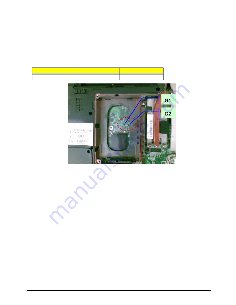
Open the back cover of the machine, and find out the HW Gap on M/B as picture.
•
Use an electric conductivity tool to short the two points of the HW Gap.
•
Plug in AC, keep the short condition on the HW Gap, and press Power Button to power on the
system till BIOS POST finish. Then remove the tool from the HW Gap.
•
Restart system. Press F2 key to enter BIOS Setup menu.
•
If there is no Password request, BIOS Password is cleared. Otherwise, please follow the steps and
try again.
NOTE:
The steps are only for clearing BIOS Password (Supervisor Password and User Password).
Item
Description
Location
G1 and G2
Clear CMOS Jumper
HDD bay
Summary of Contents for Aspire 6530 Series
Page 6: ...VI...
Page 10: ...X Table of Contents...
Page 14: ...4 Chapter 1 System Block Diagram...
Page 50: ...40 Chapter 2...
Page 85: ...Chapter 3 75 4 Grasp the module by the right side and lift up to remove...
Page 93: ...Chapter 3 83 7 Disconnect the Mic cable and remove the LCD bezel...
Page 104: ...94 Chapter 3 4 Replace the ten securing screws and screw caps on the LCD bezel...
Page 106: ...96 Chapter 3 3 Connect fan cable to the mainboard as shown...
Page 111: ...Chapter 3 101 2 Reconnect the TouchPad and Finger Print Reader FFCs as shown...
Page 120: ...110 Chapter 3 7 Turn the computer over and replace the ten screws as shown...
Page 155: ...Chapter 5 145 Jumper and Connector Locations Top View Chapter 5...
Page 156: ...146 Chapter 5 Bottom View...
Page 173: ...Chapter 6 163...
Page 220: ...210 Appendix B...
Page 222: ...212 Appendix C...