


90
Chapter 3
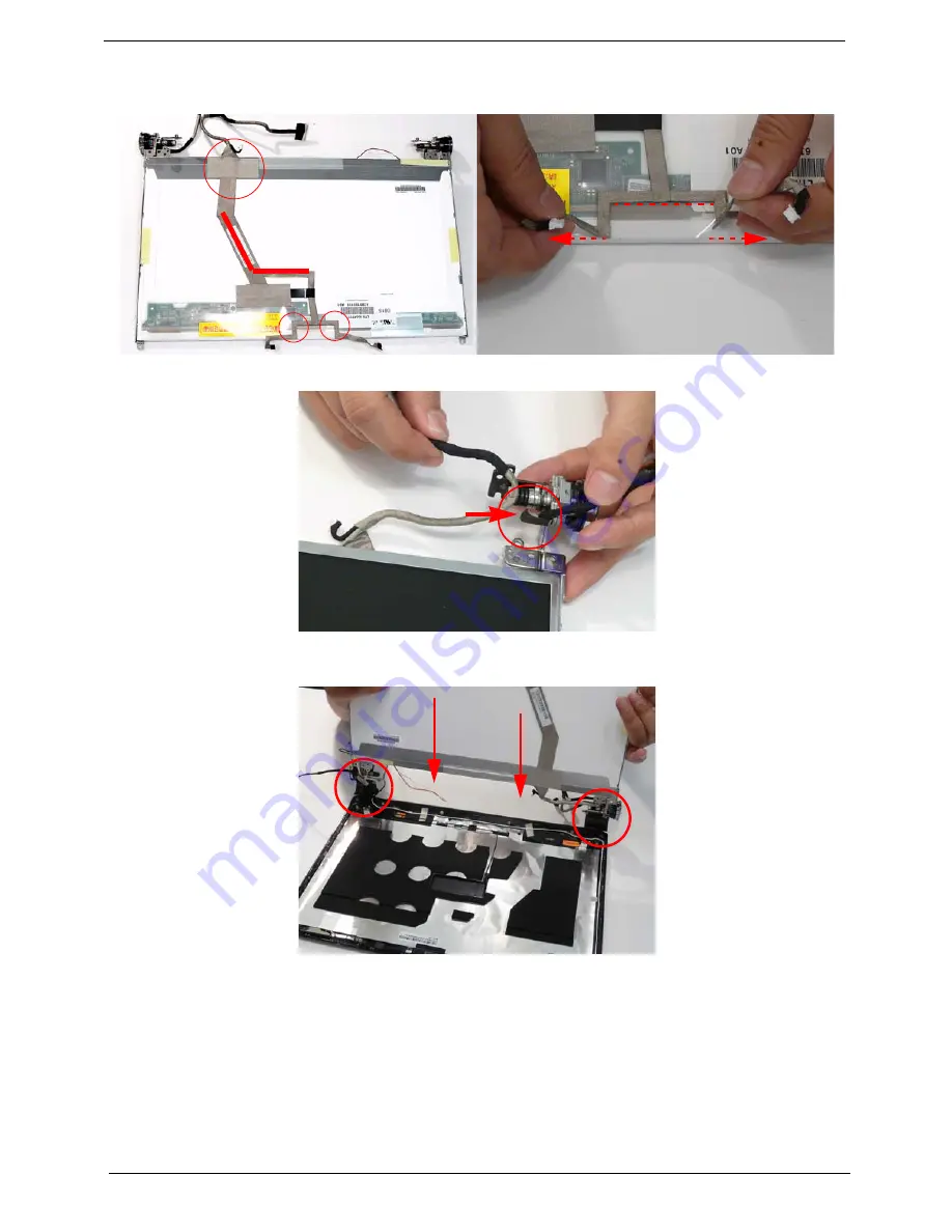
4.
Replace the remaining securing strips and press down along the length of the cable to secure it in place
ensuring the cable ends are in line with the edge of the panel.
5.
Turn the LCD Panel over and re-insert the LCD cable into the hinge retainer.
6.
Align the brackets with the alignment wells in the back panel and lower the LCD brackets into the bracket
wells as shown.
Summary of Contents for Aspire 6530 Series
Page 6: ...VI...
Page 10: ...X Table of Contents...
Page 14: ...4 Chapter 1 System Block Diagram...
Page 50: ...40 Chapter 2...
Page 85: ...Chapter 3 75 4 Grasp the module by the right side and lift up to remove...
Page 93: ...Chapter 3 83 7 Disconnect the Mic cable and remove the LCD bezel...
Page 104: ...94 Chapter 3 4 Replace the ten securing screws and screw caps on the LCD bezel...
Page 106: ...96 Chapter 3 3 Connect fan cable to the mainboard as shown...
Page 111: ...Chapter 3 101 2 Reconnect the TouchPad and Finger Print Reader FFCs as shown...
Page 120: ...110 Chapter 3 7 Turn the computer over and replace the ten screws as shown...
Page 155: ...Chapter 5 145 Jumper and Connector Locations Top View Chapter 5...
Page 156: ...146 Chapter 5 Bottom View...
Page 173: ...Chapter 6 163...
Page 220: ...210 Appendix B...
Page 222: ...212 Appendix C...